How to Fabricate a Computer Chip from Silicon
How to Make Computer Chips?
A micro-electric item that is characterized by having the ability to process data that exists in the form of electric current traveling in a specified circuit is known as a chip, processor, or a die. Chips may be made of one or more layers. The transistors and gates that make up a specific chip define how the chip will operate and its capabilities. Transistors ranging from millions to billions are arranged and connected in a given order make up a chip. The role of the transistors is to block or allow current to flow in a given direction just a normal switch does. The gate on the other hand is used to control the on and off states of the transistors thus enabling digital send, receive or process instructions to be executed. Read on!
Get Your Quote FAST! Or, Buy Online and Start Researching Today!
What is the Basic Structure of a Computer Processing Chip?
The basic structure of a processor is silicon. The transistors are built into the silicon. Because of this, silicon is a semiconductor. It can conduct electricity, but it does not completely insulate it. A computer processor needs a transistor that conducts the same amount of current as an electrical signal. This is the main reason why this process is done in a laboratory. The final chip is then shaped with a process known as photolithography.
Once a silicon wafer is made, it is then patterned. This process involves adding impurities to the silicon substrate, thereby altering the conductivity of the chip. Typically, two types of doping are used: ion-sodium doping and nitrogen doping. The doping is performed to change the electron behavior in the semiconductor. After this step, the chip is ready to use.
The first step in the PC chip making process is the purification of the silicon. A silicon ingot is cut into strips, which are then exposed to a doping process. This adds special impurities to the silicon. A computer chip can have millions of transistors, which allow it to perform tasks. Once the processing is complete, the chip will go through a number of tests, which are used to assess its power and speed.
The process for making a computer chip starts with the purification of silicon. After the silicon ingot is made, it is sliced into thin cylinders. The cylinders are then exposed to a doping process, which adds special impurities to the silicon. The resulting chips are then shaped and tested to determine their speed and power. A high-tech computer chip is ready to be used in a PC.
The first step in the process is the purification of silicon. The silicon ingot is cut into thin cylinders, or "wafers," which are the building blocks for a computer. After this, the silicon ingots undergo a doping process, which adds special impurities to the silicon. Then, the silicon cylinders are cut into the PC chip. Then, the chip is ready to be tested to see its speed and power.
The process of forming a computer chip starts with the purification of silicon. Then, the silicon ingots are sliced into thin cylinders called "wafers." These cylinders are then exposed to a doping process that adds special impurities to the silicon. Eventually, the resulting PC chip is finished and is ready to be used in computers. The process of making a computer chip begins with the purification of the silicon.
Once the silicon cylinders are finished, they are cut into strips. Each cylinder is made of a series of layers. These layers are stacked one on top of each other, creating a computer chip. The silicon cylinders are then exposed to a doping process, which adds special impurities to the silicon. The resulting silicon cylinders are then placed into molds, where the transistors are then assembled.
After the silicon wafers are purified, the silicon wafers are then exposed to a process called doping. This process changes the conductivity of the silicon substrate. It creates a silicon circuit. The atoms in a computer chip are called transistors. The chips are made of different types of material, including a semiconductor and metal. After the silicon wafers are etched, they are cooled to form a microchip.
The process of creating a computer chip starts with the purification of the silicon. Then, the silicon is sliced into a silicon cylinder. Finally, the cylinders are exposed to a doping process, which adds special impurities to the silicon substrate. The transistors are the most essential part of a computer. The transistors in the PCs power everything today. It is made up of billions of individual parts.
The process of fabricating a PC chip starts with the melting of silicon ingots. The silicon is then refined to the best surface for a PC chip. Then, a layer of photoresist is applied to the surface of the silicon. The photoresist then becomes soluble and is washed away with a solvent. Then, a hard pattern is then applied to the silicon wafer.
Are Silicon Wafers Chips?
Silicon wafers and chips are related but distinct components in the world of electronics and semiconductors. Here's how they differ:
-
Silicon Wafers: These are thin slices of semiconductor material, usually silicon, used as a substrate for the fabrication of integrated circuits. They serve as the base on which chips or integrated circuits are built. Crafted in a range of sizes, silicon discs are meticulously measured by the inch or millimeter across their round expanse. Before any circuitry can be added, they are just plain, unpatterned wafers.
-
Chips or Integrated Circuits: A chip, also known as an integrated circuit or microchip, is a small piece of semiconductor material (usually silicon) on which an electronic circuit is etched or implanted. These circuits are created through a process called photolithography, where layers of materials are added, removed, or altered on the wafer in a specific pattern. Once the circuitry is in place, the wafer is cut into many individual chips.
Essentially, the journey of chips begins with their foundational element, the silicon wafer, which is intricately transformed to form the heart of our electronic devices. Starting as simple silicon discs, these wafers embark on an intricate journey of transformation, morphing through a series of elaborate steps into the sophisticated circuits that power our gadgets.

A Layman's Guide to Fabricating Computer Chips from Silicon
Before a chip is made, engineers have to carefully scrutinize the provided specifications to ascertain that they are attainable. The first specification is the chip blueprint where several questions have to be answered such as why the specified chip has to be made. Also, the number of transistors that can be fabricated on the chip has to be determined. The size of the chip has to be specified. Besides the technology that is to be used to make the die is to be specified. The lead time, manufacturing, and testing center are also important parameters that should be specified. It is therefore prudent to link the customers, manufacturer, and software companies in the whole process.
Given that the specifications have already been outlined, engineers move forward to come up with a logic design that is a skeleton representation of the many transistors and the respective connections that exist in the chip to control how electricity flows. A physical illustration of the chips' logic design layer is then prepared. Afterward, a mask for each layer is made that will aid in the photolithography process. Computer-aided design (CAD) is then used to validate the chip design that has been achieved so far. Further, CAD aids in testing and simulation of the chip thus verifying if the desired goals have been achieved.
To make chips, special dust-free rooms called cleanrooms are needed. Dust particles deposited on the surface of the chip do damage formed complex circuits thus introducing failures. Certain measures have been undertaken to minimize dust in the clean rooms such as circulating purified air to the rooms and ensuring that the technicians do have special clothing (bunny suits). The purified air enters the rooms through the ceiling and leaves through the tiled floor. These measures minimize human hair, lint, or dust in the clean rooms such that it is possible to have one small particle in one cubic foot air volume.

Figure 1: An illustration of how the clean room floors look like. (Intel, 2012)
Given applications of electronic devices require wafers that meet a specific application. The wafer size, the dopant used to make the wafer, the orientation of the wafer elements, or the die count are some of the properties that a customer has to keenly consider as he or she decides to buy silicon wafers. The surface area of a wafer determines the number of integrated circuits that can be fabricated from a wafer (Insights, 2020). On the other hand, the cost of making the wafers does increase with the increasing surface area though the cost increase is not proportional to the surface area. The current maximum wafer diameter is at three hundred millimeters. Different wafer suppliers have different capacities so one should inquire if the desired specifications can be achieved.
Wafers are circular in physical appearance with maximum diameters of three hundred millimeters and minimum diameters of twenty-five millimeters. Apart from the stated diameters, wafer diameters of 51mm, 100mm, 130mm, 200mm, or 76mm also do exist. Wafer diameters of 300mm as particularly suitable for use in data centers, contact image sensors, or advanced logic devices. Those with diameters less than or equal to 200mm are suitable in the Internet of things applications or automotive fields. Although the diameters of the wafers are measured in terms of millimeters, the common reference of the diameter is based on the nearest inch. Fabrication plants are described by the wafer diameter they make such as a six-inch plant. Concerning the thickness of a wafer, a wafer has to support its weight without failure, particularly during handling. Large wafers have to be thicker than small wafers.
The number of dies that can be obtained from a wafer needs to be more to reduce the cost of making many wafers. Since the dies have to have straight edges, the wafers that are formed at the edges of the wafer are usually incomplete. The nature in which the atoms of silicon are aligned has to be considered as it does affect the structural and electronic characteristics of a device. By considering the orientation of silicon crystal, the path of the transporting ions can be determined. Besides, it becomes easy to do dicing to the wafers as the process is done along the discontinuity planes. Some wafer suppliers may be ready to supply the orientation information of the silicon wafers procured thus if this is a requirement, such suppliers may be suitable choices.
To control the electrical properties of silicon wafer-based devices, dopants are included thus acting as impurities. Dopants may be classified as n-type (i.e. Antimony, Arsenic, or Phosphorus) or p-type (i.e. Gallium or Boron). The effects of doping are an increase in the concentration of ion carriers that do improve the electrical conductivity of a wafer. The concentration of a wafer is shown where the negative subscript indicates a lightly doped wafer. On the other hand, a positive subscript implies a highly doped wafer. The concentrations for doping range from 1013 to 1016 atoms of the dopant per cubic centimeter. Not all silicon suppliers have the capability of incorporating all of the mentioned dopants thus one should select those that use the desired dopants.
The silicon ingot growth method is another parameter when one may use to select a wafer supplier. Two methods may be used to obtain the wafers i.e. the Czochralski zone process or the float zone process. Each method has its advantages and limitations such as the low production cost and good thermal stress being favorable properties when wafers are obtained using the Czochralski process. However, this method does not produce high-quality wafers as the float zone wafer does. Different silicon wafer suppliers may have invested in a specific method hence it is wise to inquire about the method to be used to fabricate the silicon wafer.
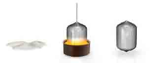
Figure 2: Sand to ingot process illustration. (Intel, 2012)
Next, the ingot is divided into thin silicon discs with a thickness of less than one millimeter. The sliced discs are known as wafers and since they are made of silicone material, they become silicon wafers. The wafers then have to be polished to remove any introduced flaws such as an irregular surface as a result of the slicing process. Some chip manufactures can source for the wafers externally such as Intel while others such as UniversityWafer do supply ready-made wafers.

Figure 3: Ingot to wafer process illustration. (Intel, 2012)
After a wafer has been obtained, a specific pattern has to be imprinted on it through a process known as photolithography. A photoresist material that is characterized as light-sensitive and etch-resistant is introduced to the surface of the wafer. Then the hardening of the photoresist is done and some areas are subjected to ultraviolet light that makes it soluble. When light passes through the mask and lens, it causes the circuit patterns to be printed on the layers of the wafer making up the chip. The soluble photoresist material is then removed chemically and a patterned photoresist material is left behind similar to what the mask looked like.

Figure 4: Photolithography process. (Intel, 2012)
To alter the electrical and thermal conductive properties of the silicon wafer, positively or negatively charged atoms (ions) are introduced to the surface of the wafer that is not coated with the photoresist material. When the implantation process is done, the photoresist material is removed leading to some wafer areas being doped with impurities. The photolithography process is then done to the single wafer to the scale of a single transistor. Repeated etching and hard mask removal processes are done to obtain a tall and thin fin of silicon that has the channel type of the transistor. The resulting wafer is then exposed to oxygen in a furnace where silicon dioxide layers are formed that serve various roles such as forming a temporary gate dielectric of an insulation layer. The gate-last operation is done in preparation for the formation of a final gate. Atomic layer deposition procedure is then undertaken where layers of high-k dielectric material are applied to the wafer surface. Areas where the dielectric material is deposited such as on the silicon dioxide surfaces are then removed by etching. A metal gate electrode is thus formed that contributes to an improvement of the chip performance and a reduction in the leakage tendency. Holes are then chemically etched above the transistor through the insulating layer. The holes are filled with copper through electroplating process to form metal connections with neighboring transistors. A polishing procedure is then done to eliminate the excess material after electroplating and in the process, a given pattern of copper is revealed.
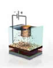
Figure 5: Electroplating procedure. (Intel, 2012)
Given that chip processing has been accomplished, individual chips are then tested to verify the functionality. Since a wafer has many dies, the dies have to be separated from each other through slicing. The good dies are then forwarded for packaging. To make a complete processor, the heat spreader, the die, and the substrate are all combined. The substrate has the role of establishing mechanical and electrical connections with the outside world so that the processor can interact with the designed system. The heat spreader aids in dissipating the heat generated by the processor. A final functional test of the processor is then done just to make sure it is functional with regards to power and functionality. Lastly, the processors with the same technical and physical specifics are categorized to specific trays for transportation to the expected destination.
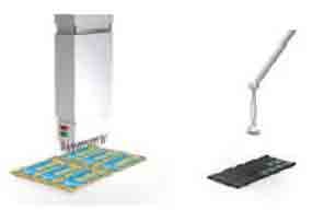
Figure 6: An illustration of the chip testing and sorting process. (Intel, 2012)
References
Intel. (2012). From sand to Circuits - How Intel Makes Chips. Arizona: Intel Corporation.