
Get Your Custom Wafer Quote FAST!
Need help choosing the right custom wafer size, material, thickness, orientation, dopant, resistivity, or surface finish? UniversityWafer supplies substrates for semiconductor research, MEMS, photonics, sensors, power devices, thin-film deposition, university laboratories, and production development.
Available options may include silicon, silicon carbide, sapphire, gallium arsenide, glass, fused silica, SOI wafers, coated wafers, epitaxial structures, and custom diced pieces. We can help identify a suitable wafer specification based on your application and equipment requirements.
Information to Include in Your Request
- Material: Silicon, SiC, sapphire, GaAs, glass, fused silica, SOI, or another substrate
- Wafer size: 3-inch, 4-inch, 6-inch, 8-inch, or 12-inch
- Thickness: Standard or custom thickness and tolerance
- Electrical properties: P-type, n-type, dopant, and resistivity range
- Crystal orientation: Common options include <100>, <110>, and <111>
- Surface finish: Single-side polished, double-side polished, as-cut, lapped, or etched
- Layers or coatings: Thermal oxide, silicon nitride, epitaxial silicon, metals, or other deposited films
- Quantity and application: Include the number of wafers or pieces and how they will be used
Equipment compatibility should be verified before ordering. Tell us which processing tools, temperatures, chemicals, or handling systems will be used so we can better understand your requirements.
Get Your Custom Wafer Quote FAST! Or, Buy Online and start researching today.
How to Choose the Right Custom Wafer
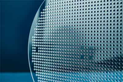
Choosing a custom wafer requires more than selecting a diameter. The substrate material, wafer size, thickness, crystal orientation, dopant, resistivity, surface finish, flatness, and any deposited layers must all be compatible with your application and fabrication equipment.
A wafer that is suitable for basic thin-film research may not meet the requirements of MEMS fabrication, RF devices, power electronics, photonics, integrated circuits, or high-temperature processing. Defining the full specification before ordering helps reduce processing problems, unnecessary cost, and delays.
Start With the Application
The intended process or device should guide every wafer specification. Before selecting a substrate, determine what the wafer must do during fabrication and in the finished device.
- Semiconductor devices: Consider dopant type, resistivity, crystal orientation, surface quality, and compatibility with lithography and thermal processing.
- MEMS: Evaluate wafer thickness, total thickness variation, crystal orientation, mechanical strength, and whether a buried oxide layer is required.
- Photonics: Consider optical transparency, refractive index, surface roughness, thickness uniformity, and deposited optical layers.
- Power electronics: Review bandgap, thermal conductivity, resistivity, epitaxial requirements, and high-temperature stability.
- Thin-film research: Confirm surface finish, substrate chemistry, deposition temperature, film adhesion, and coefficient of thermal expansion.
- Solar-cell research: Consider material purity, conductivity type, resistivity, surface texture, thickness, and minority-carrier requirements.
Researchers working in MEMS, photonics, sensors, RF devices, and semiconductor fabrication may require very different wafers even when using the same substrate material.
Choose the Wafer Material
Material selection affects electrical behavior, optical performance, thermal management, mechanical stability, processing temperature, and the wafer sizes that are practical or commonly available.
Silicon Wafers
Silicon wafers are widely used because they are available in many diameters, dopant types, resistivity ranges, crystal orientations, thicknesses, and surface finishes. Silicon is commonly selected for integrated circuits, MEMS, sensors, solar cells, thin-film deposition, and university research.
Silicon substrates may be supplied as Czochralski-grown, Float Zone, intrinsic, high-resistivity, heavily doped, single-side polished, double-side polished, or with thermal oxide, silicon nitride, epitaxial silicon, and other deposited layers.
Silicon Carbide
Silicon carbide wafers are used for high-power, high-frequency, and high-temperature devices. Important SiC specifications include polytype, conductivity type, orientation, off-axis angle, resistivity, defect requirements, surface finish, and whether an epitaxial layer is needed.
Gallium Arsenide and Other III-V Materials
Gallium arsenide wafers are commonly selected for RF electronics, optoelectronics, lasers, photodetectors, and high-efficiency photovoltaic research. III-V substrates generally have different diameter, thickness, orientation, and surface-finish options than silicon.
Sapphire, Glass, and Fused Silica
Sapphire wafers offer high hardness, electrical insulation, optical transparency, and thermal stability. They are used for GaN epitaxy, RF devices, optical windows, sensors, and research requiring a durable insulating substrate.
Glass wafers and fused silica wafers are useful for microfluidics, optics, wafer bonding, displays, sensors, and applications requiring electrical insulation or optical transmission.
Select the Wafer Diameter
Wafer diameter affects equipment compatibility, usable processing area, handling, material cost, and the number of devices that can be fabricated on each substrate. Larger wafers do not automatically provide the best value for every project.
| Nominal Size | Diameter | Typical Uses | Selection Considerations |
|---|---|---|---|
| 2 inch | 50.8 mm | Specialty materials, early research, small-scale experiments | Useful when material cost or availability limits larger diameters |
| 3 inch | 76.2 mm | University research, process development, specialized production | Lower material cost and convenient laboratory handling |
| 4 inch | 100 mm | MEMS, sensors, photonics, thin-film processing | Common in research and specialty fabrication equipment |
| 6 inch | 150 mm | MEMS, power devices, compound semiconductors, production development | Provides more usable area while remaining common in specialty processing |
| 8 inch | 200 mm | MEMS, analog devices, RF, mature semiconductor production | Requires compatible 200 mm handling and processing equipment |
| 12 inch | 300 mm | High-volume silicon semiconductor manufacturing | Best suited to facilities designed specifically for 300 mm processing |
UniversityWafer supplies several diameter-specific silicon products, including 3-inch, 4-inch, 6-inch, 8-inch, and 12-inch silicon wafers.
Verify Equipment Compatibility
The wafer must fit every tool used in the process, not only the first one. Confirm compatibility with deposition systems, oxidation furnaces, lithography tools, spin coaters, etchers, wafer bonders, metrology equipment, dicing systems, cassettes, vacuum chucks, and robotic handlers.
Before ordering, verify the following:
- Maximum and minimum wafer diameter accepted by each tool
- Permitted wafer-thickness range
- Whether the equipment uses a notch, flat, edge grip, or vacuum chuck
- Whether carriers or adapters are required
- Backside surface and coating restrictions
- Bow, warp, and flatness limits
- Temperature and chemical compatibility
A non-standard diameter or unusually thin wafer may require a carrier wafer, temporary bonding, a custom chuck, or manual handling. These requirements should be identified before the wafer specification is finalized.
Specify Wafer Thickness
Wafer thickness affects mechanical strength, thermal behavior, device geometry, handling, dicing, bonding, and compatibility with fabrication equipment. Standard thickness often depends on wafer diameter and material, but custom thicknesses may be available.
Thinner wafers may be needed for:
- Backside-illuminated devices
- 3D integration and wafer stacking
- Flexible or lightweight devices
- Reduced optical path length
- Improved heat transfer
- Specialized MEMS structures
Thicker wafers may be preferred when mechanical stability, reduced breakage, deep etching, aggressive polishing, or repeated high-temperature processing is important.
Choose Crystal Orientation
Crystal orientation describes how the wafer surface is aligned with the silicon crystal lattice. Common silicon orientations include <100>, <110>, and <111>.
- <100>: Frequently used for CMOS, general semiconductor fabrication, oxidation, and many MEMS processes.
- <110>: Used in selected device structures, anisotropic etching studies, and specialized research.
- <111>: Chosen for applications requiring its specific atomic arrangement, mechanical behavior, or etching characteristics.
Orientation should be selected according to the device design, etching chemistry, epitaxial process, mechanical requirements, and desired surface properties.
Select Dopant Type and Resistivity
Silicon wafers may be supplied as p-type, n-type, intrinsic, or semi-insulating depending on the material. The dopant and concentration determine the wafer’s electrical conductivity and resistivity.
- P-type silicon: Commonly doped with boron.
- N-type silicon: Commonly doped with phosphorus, arsenic, or antimony.
- High-resistivity silicon: Used for RF, detectors, photonics, and applications requiring reduced electrical losses.
- Heavily doped silicon: Used where a conductive substrate or low-resistance electrical path is needed.
Resistivity should be specified as a range in ohm-centimeters (Ω·cm). Researchers should also confirm whether radial resistivity variation or dopant uniformity is important to the process.
Choose the Surface Finish
Surface condition influences coating adhesion, lithography, bonding, optical performance, epitaxial growth, and surface characterization.
- Single-side polished (SSP): One mirror-polished device surface with a less highly finished backside.
- Double-side polished (DSP): Both sides polished for optical, MEMS, bonding, or double-sided processing.
- As-cut: Unpolished material suited to selected mechanical, development, or low-cost applications.
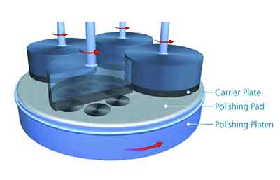
- Lapped or etched: Intermediate finishes used where mirror polishing is unnecessary.
Surface roughness, particles, scratches, haze, edge chips, pits, and contamination limits should be included when they are important to the experiment.
Understand Wafer Grade
Wafer grade should match the sensitivity of the process. Using a higher grade than necessary may increase cost without improving the experiment, while using a lower grade may introduce unwanted variation.
- Prime grade: Intended for demanding fabrication, advanced lithography, epitaxy, and processes requiring tight surface and dimensional specifications.
- Test grade: Suitable for equipment testing, process development, deposition trials, training, and less demanding research.
- Reclaimed grade: Previously processed wafers that have been stripped and repolished for compatible development or monitoring applications.
- Mechanical grade: Used for handling trials, equipment setup, carrier applications, and processes where electronic properties are not critical.
Review Flatness and Dimensional Specifications
Diameter and thickness alone do not fully describe the physical geometry of a wafer. Precision processes may also require limits for:
- Total thickness variation (TTV)
- Bow
- Warp
- Site flatness
- Edge profile
- Notch or flat orientation
- Surface roughness
Tight flatness and TTV specifications are especially important for wafer bonding, photolithography, thin-film uniformity, precision metrology, and devices processed on both wafer surfaces.
Consider Coatings and Custom Layers
Many projects require a processed wafer rather than a bare substrate. Custom wafers may include:
- Thermal oxide
- Silicon nitride
- Epitaxial silicon
- Deposited metals
- PECVD or LPCVD dielectric films
- Transparent conductive coatings
- Adhesion and seed layers
- Patterned films or alignment marks
- Custom multilayer stacks
When requesting a coated wafer, specify the film material, target thickness, thickness tolerance, deposition method, wafer side, stress requirements, surface preparation, and whether the backside must remain uncoated.
Full Wafers, Pieces, and Custom Shapes
A full wafer may not be necessary for every research project. Smaller quantities of material may be supplied as half wafers, quarter wafers, diced pieces, coupons, squares, rectangles, or custom shapes when compatible with the material and processing requirements.
Diced pieces can reduce material cost for deposition, microscopy, spectroscopy, sensor development, and proof-of-concept experiments. However, researchers should confirm whether their tools can safely hold and process non-circular substrates.
Match Wafer Size to Production Volume
Production volume influences the most practical wafer diameter, but equipment compatibility and material availability remain equally important.
- Research and early development: Smaller wafers or diced pieces may reduce material cost and allow more experimental variations.
- Pilot production: Intermediate diameters may provide more usable area while remaining compatible with specialty fabrication tools.
- High-volume manufacturing: Larger wafers can increase the number of devices processed per cycle when the complete production line supports that diameter.
A larger wafer only improves efficiency when the facility, tooling, process uniformity, and expected yield support the larger format.
Custom Wafer Ordering Checklist
Providing a complete specification helps the supplier identify the closest available wafer or determine whether custom processing is required.
| Specification | Information to Provide |
|---|---|
| Material | Silicon, SiC, GaAs, sapphire, glass, fused silica, SOI, or another substrate |
| Diameter or dimensions | Full-wafer diameter or diced-piece length and width |
| Thickness | Target thickness and acceptable tolerance |
| Orientation | Crystal plane, off-axis angle, notch, or flat requirements |
| Electrical properties | Conductivity type, dopant, resistivity, and uniformity requirements |
| Surface finish | SSP, DSP, as-cut, lapped, etched, or another finish |
| Grade | Prime, test, reclaimed, mechanical, optical, or research grade |
| Films and coatings | Material, thickness, wafer side, deposition method, and tolerance |
| Flatness | TTV, bow, warp, or site-flatness limits |
| Quantity | Number of wafers or pieces needed |
| Application | Process, device, temperature range, chemicals, and equipment used |
Common Custom Wafer Selection Mistakes
- Choosing a diameter before confirming equipment compatibility
- Ordering by resistivity without specifying p-type or n-type material
- Confusing crystal orientation with wafer flat or notch orientation
- Requesting DSP wafers when only one polished surface is needed
- Ignoring bow, warp, or TTV for bonding and lithography
- Failing to specify whether coatings are required on one side or both sides
- Selecting prime-grade material for a process that only requires test grade
- Ordering thin wafers without planning for temporary bonding or carrier support
- Assuming every material is available in every diameter
Choosing Wafers for Common Applications
Research and Process Development
University laboratories and process-development teams often benefit from smaller wafers, test-grade material, or diced pieces. These formats can reduce material consumption while still supporting deposition, lithography, etching, characterization, and proof-of-concept device fabrication.
MEMS and Sensors
MEMS researchers should evaluate orientation, thickness, TTV, wafer flatness, polish, mechanical strength, and compatibility with deep reactive-ion etching, wet anisotropic etching, wafer bonding, and backside processing.
Silicon-on-insulator wafers are frequently selected when the device layer and buried oxide thickness define the mechanical structure or provide electrical isolation.
Power and RF Devices
Power and RF applications may require high-resistivity silicon, silicon carbide, gallium nitride structures, or substrates with specialized epitaxial layers. Thermal conductivity, defect density, orientation, doping, and layer structure can be as important as wafer diameter.
Photonics and Optical Research
Optical applications may require DSP substrates, low surface roughness, controlled thickness, optical-grade material, transparent substrates, or coatings with precise refractive-index and thickness requirements.
Frequently Asked Questions About Custom Wafers
What is the best wafer size for university research?
The best size depends on the laboratory equipment, process area needed, substrate material, and budget. Smaller wafers and diced pieces are often practical for early research, while larger wafers may be needed for equipment compatibility or higher device counts.
Can wafers be supplied in custom thicknesses?
Custom thicknesses may be available depending on the material, diameter, target tolerance, quantity, and required surface finish. Very thin wafers may require temporary bonding or carrier support during processing.
Can I order partial wafers or diced pieces?
Many materials can be supplied as half wafers, quarter wafers, coupons, squares, rectangles, or other diced pieces. Dimensions, edge quality, orientation, and quantity should be included in the request.
Should I choose SSP or DSP wafers?
SSP wafers are appropriate when only one polished processing surface is needed. DSP wafers are generally selected for optical transmission, double-sided lithography, precision bonding, MEMS, or processes requiring controlled front-to-back parallelism.
What information is needed for a custom quote?
Include the material, diameter, thickness, orientation, dopant, resistivity, polish, grade, coatings, flatness requirements, quantity, and intended application. Providing complete specifications helps prevent delays and makes it easier to identify available alternatives.
Request Custom Wafer Specifications
UniversityWafer supplies semiconductor and optical substrates for research, prototyping, education, and production. Available options include silicon, silicon carbide, sapphire, gallium arsenide, glass, fused silica, SOI, coated wafers, epitaxial structures, and diced pieces.
When requesting a quote, include as much technical information as possible. If the exact specification is unavailable, a closely matched diameter, thickness, orientation, resistivity, surface finish, or coated-wafer configuration may be recommended.
Related Wafer Selection Resources
- Silicon Wafers for Research and Production
- Silicon-on-Insulator (SOI) Wafers
- Silicon Carbide (SiC) Wafers
- Gallium Arsenide (GaAs) Wafers
- Sapphire Wafers
- Thermal Oxide Silicon Wafers
- Silicon Nitride Coated Wafers
- Silicon Epitaxial Wafers
- Polished Silicon Wafers
- Heavily Doped Silicon Wafers
- MEMS Wafer Applications
- Photonic Device Substrates
- Semiconductor Manufacturing Process