Example Requested Specification:
- Diameter: 150 mm (6 inch)
- Material: Silicon
- Wafer identification: Notch
- Quantity: 10 wafers or more
- Intended use: CMOS-compatible process and wafer-cutting development
UniversityWafer supplies silicon wafers and SOI substrates for CMOS research, semiconductor fabrication, and device development. Choose substrate specifications including crystal orientation, doping type, resistivity, thickness, surface finish, and oxide layers for applications such as MOSFET fabrication, integrated circuits, CMOS image sensors, MEMS, and microelectronics research.

Silicon wafers are the dominant substrate platform for complementary metal-oxide-semiconductor (CMOS) technology. Their widespread use is supported by mature silicon processing, precise doping control, and the ability to form a high-quality silicon dioxide (SiO2) interface for MOS device structures.
UniversityWafer supplies silicon substrates for CMOS-related research, microfabrication, process development, equipment qualification, and other semiconductor applications. Researchers can specify parameters such as wafer diameter, crystal orientation, conductivity type, resistivity, thickness, surface finish, and wafer identification features such as notches or flats.
One researcher requested 150 mm (6-inch) silicon wafers with a notch rather than a conventional primary flat. The wafers were intended for use in a CMOS fabrication environment and as lower-cost test substrates during development of a wafer-cutting process before processing more expensive silicon carbide (SiC) wafers .
Example Requested Specification:
A representative substrate supplied for this type of research was a 150 mm, 650 µm thick, single-side-polished (SSP), P-type Si(100) wafer with 1–100 Ω·cm resistivity. Actual wafer requirements should be selected according to the intended fabrication process and equipment.
The appropriate substrate specification depends on the device architecture and fabrication process. Important wafer parameters can include crystal orientation, dopant type, resistivity, thickness, total thickness variation (TTV), surface roughness, and cleanliness.
Si(100) is widely used for conventional MOS and CMOS fabrication because the Si(100)/SiO2 interface has historically provided favorable electrical characteristics for MOS structures. However, substrate orientation and electrical specifications should always be selected for the particular process flow and device design.
Silicon-on-insulator (SOI) wafers are another important platform for CMOS research. An SOI substrate typically consists of a thin crystalline silicon device layer separated from the silicon handle wafer by a buried oxide (BOX) layer.
The buried insulating layer provides electrical isolation and can reduce parasitic junction capacitance compared with comparable bulk-silicon device structures. These characteristics make SOI useful for research involving low-power electronics, RF devices, fully depleted SOI (FD-SOI), MEMS, and other specialized semiconductor technologies.
Sapphire substrates may also be used in semiconductor research environments where electrical insulation, optical transparency, chemical stability, or high-temperature capability is useful. Sapphire, however, is not a direct replacement for conventional silicon CMOS substrates.
When sapphire or another non-silicon material is introduced into a CMOS fabrication environment, contamination control can be a critical qualification requirement. Fabrication facilities may establish limits for metallic contaminants such as Fe, Ni, Cu, Cr, Na, K, Ca, and Zn because unwanted contamination can affect semiconductor device performance, yield, and reliability.
Surface metallic contamination and bulk material purity are different specifications and should not be treated as interchangeable.
A bulk purity value such as 99.996% therefore does not by itself demonstrate that a wafer meets a specified surface-metal contamination limit. If a CMOS facility requires a numerical contamination limit, the substrate should be evaluated using an appropriate analytical method and documented against that specific requirement.
Semiconductor cleaning processes are designed to reduce particles, organic residues, ionic contamination, and trace metals before critical processing. The appropriate chemistry and cleaning sequence depend on the substrate material and fabrication requirements.
For silicon processing, established RCA-type cleaning sequences and other semiconductor-grade wet-cleaning methods are commonly used. Sapphire may require different optimized cleaning procedures because its surface chemistry differs from silicon.
When extremely low metallic contamination levels are required, researchers should specify the target elements, maximum allowable surface concentration, analytical method, sampling requirements, and required documentation when requesting a quote.
CMOS circuits consume energy through both dynamic switching power and static leakage power. A useful first-order expression for dynamic switching power is:
Pdynamic ≈ α CL VDD2 f
where α is the switching activity factor, CL is the effective switched capacitance, VDD is the supply voltage, and f is the switching frequency.
Because dynamic power scales approximately with the square of supply voltage, reducing VDD can significantly lower switching power. Designers also reduce power through lower capacitance, clock gating, power gating, optimized transistor structures, and architectural techniques such as dynamic voltage and frequency scaling (DVFS).
Heat generated by CMOS devices must ultimately be transferred through the die, package, thermal interface materials, heat spreaders, and cooling system. High-performance devices may use flip-chip packaging, integrated heat spreaders, vapor chambers, forced-air cooling, or liquid cooling, depending on the device power density and operating environment.
Advanced device technologies such as FinFETs, gate-all-around (GAA) transistors, and FD-SOI can improve electrostatic control and enable different power-performance tradeoffs, while packaging and thermal design remain essential for controlling operating temperature.
UniversityWafer supplies semiconductor substrates for university, laboratory, and industrial CMOS research. Available options include silicon wafers, SOI wafers, oxide-coated wafers, and other specialized substrates for microelectronics, MOS device fabrication, process development, and semiconductor research.
Researchers can request custom specifications including wafer diameter, orientation, dopant type, resistivity, thickness, polish, oxide thickness, and other substrate parameters required for their process.
Get Your CMOS Substrate Quote FAST! Or, Buy Wafers Online and start researching today!
CMOS (complementary metal-oxide-semiconductor) is a semiconductor device and integrated-circuit technology based on complementary n-channel and p-channel MOSFETs. CMOS is not itself a semiconductor material; instead, it is a method of designing and fabricating electronic circuits, most commonly on silicon wafers .
In a basic CMOS logic gate, complementary nMOS and pMOS transistor networks are arranged so that, ideally, there is no continuous direct-current path from the supply voltage to ground in either stable logic state. This architecture provides low static power consumption compared with many older logic technologies, although modern CMOS circuits still consume power through switching, leakage currents, and short-circuit currents during transitions.
CMOS technology is used throughout modern electronics, including microprocessors, microcontrollers, memory interfaces, analog and mixed-signal circuits, RF electronics, image sensors, and system-on-chip (SoC) devices.
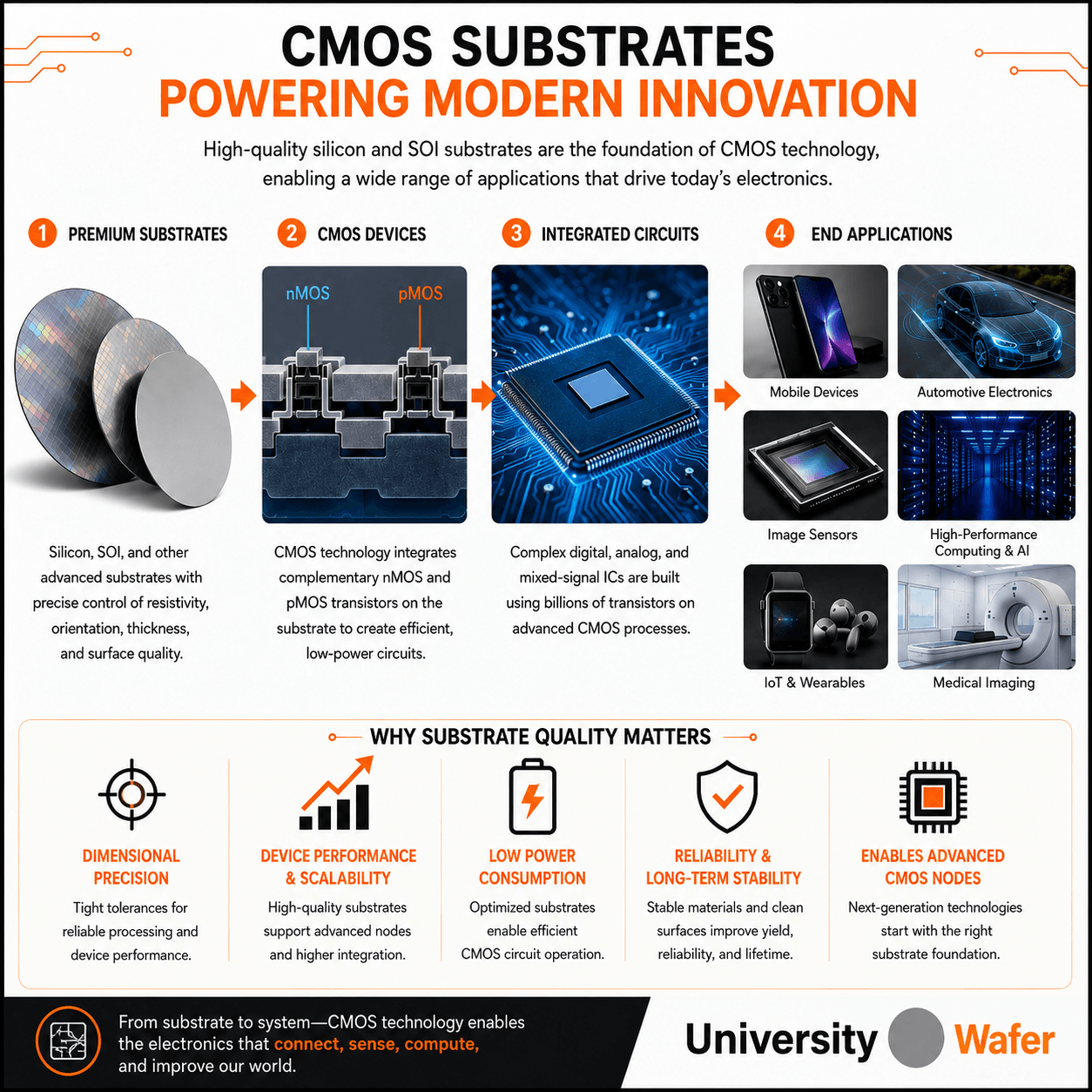
Silicon remains the dominant substrate material for CMOS manufacturing because it combines suitable semiconductor properties with an exceptionally mature fabrication infrastructure.
One particularly important advantage is silicon's ability to form a high-quality interface with thermally grown silicon dioxide (SiO2). This material system played a fundamental role in the development of reliable MOS devices and remains important in semiconductor processing, even though advanced CMOS technologies now use materials such as high-k gate dielectrics and metal gates.
Silicon also supports precise control of conductivity through doping, high-quality single-crystal wafer manufacturing, large wafer diameters, established lithography and etching processes, and a highly developed semiconductor manufacturing ecosystem.
CMOS research can require different substrate specifications depending on the device architecture and process flow. Important parameters may include:
P-type silicon wafers and N-type silicon wafers can both be used as starting substrates depending on the CMOS process and device structure.
Silicon-on-insulator (SOI) wafers provide an alternative to conventional bulk silicon. A typical SOI wafer consists of a crystalline silicon device layer separated from a handle substrate by a buried oxide (BOX) layer.
The insulating BOX layer provides electrical isolation and can reduce parasitic junction capacitance. Depending on the device architecture, SOI technology can provide advantages in power consumption, switching performance, RF behavior, isolation, and radiation response.
Fully depleted SOI (FD-SOI) uses a very thin silicon device layer that can be fully depleted during transistor operation. FD-SOI also supports body-bias techniques that can adjust transistor threshold behavior, allowing designers to trade performance against power consumption.
CMOS image sensors are generally fabricated using crystalline silicon because silicon is photosensitive across much of the visible and near-infrared spectrum and is compatible with mature CMOS manufacturing.
A CMOS image sensor contains an array of photosensitive pixels. Within each pixel, a photodiode converts incident photons into charge carriers. The accumulated signal is then read using CMOS circuitry and processed by column-level and/or on-chip electronics.
Depending on the sensor design, manufacturers may use bulk silicon, epitaxial silicon, or specialized high-resistivity silicon structures. Epitaxial layers and higher-resistivity material can be particularly useful when device designers need greater depletion depth or improved charge collection.
Modern CMOS image sensors may also use backside illumination (BSI). In a BSI architecture, light enters from the back side of a thinned silicon sensor rather than passing through front-side interconnect structures before reaching the photodiodes. This architecture can improve optical efficiency, particularly as pixel dimensions become smaller.
The fundamental switching devices in conventional CMOS circuits are MOSFETs . CMOS logic combines n-channel MOSFETs (nMOS) and p-channel MOSFETs (pMOS) into complementary pull-down and pull-up networks.
In a simple CMOS inverter, a low input causes the pMOS transistor to conduct while the nMOS transistor is off, producing a high output. A high input turns the nMOS transistor on and the pMOS transistor off, producing a low output.
Ideally, significant current flows from the supply during switching rather than continuously in a stable state. Real CMOS devices also exhibit leakage currents, however, and these become increasingly important as transistor dimensions and operating voltages are scaled.
CMOS became dominant partly because of its favorable power characteristics and ability to integrate very large numbers of transistors. Dynamic switching power can be approximated by:
Pdynamic ≈ α CL VDD2 f
where α is switching activity, CL is effective switched capacitance, VDD is supply voltage, and f is switching frequency.
Modern CMOS scaling is increasingly constrained by leakage, electrostatic control, interconnect resistance and capacitance, thermal management, variability, and manufacturing complexity. These challenges have driven development beyond conventional planar MOSFETs.
Advanced CMOS technologies increasingly use three-dimensional transistor architectures to improve electrostatic control of the channel. FinFETs surround the channel with the gate on multiple sides, while gate-all-around (GAA) transistors provide even greater gate control by surrounding nanosheet or nanowire channels.
These architectures help control short-channel effects as transistor dimensions shrink. Advanced CMOS also incorporates innovations in gate dielectrics, contacts, interconnects, strain engineering, packaging, and device materials.
Silicon continues to dominate CMOS manufacturing, but researchers are investigating other semiconductor materials for selected device layers and future transistor architectures.
Germanium (Ge) has high carrier mobility, particularly for holes, and has been investigated for high-performance transistor channels and heterogeneous integration. Integration challenges include interface control, process compatibility, and manufacturing complexity.
III-V semiconductors such as gallium arsenide (GaAs) and indium phosphide (InP) offer high electron mobility and are important for RF, photonic, and high-speed electronic applications. Integrating III-V materials with silicon CMOS is an active area of research.
Atomically thin semiconductors such as transition-metal dichalcogenides including MoS2 and WSe2 are being studied for extremely thin transistor channels. Their potential advantages include excellent electrostatic control at very small thicknesses, although large-scale manufacturing, contacts, defects, and integration remain significant research challenges.
These materials should therefore be viewed primarily as research candidates for future or heterogeneous electronic technologies rather than established replacements for silicon CMOS.
Silicon and SOI substrates support a broad range of CMOS and CMOS-compatible research applications, including:
UniversityWafer supplies silicon wafers , SOI substrates , oxide-coated wafers, high-resistivity silicon, and other semiconductor substrates for CMOS research, microfabrication, sensor development, and process engineering.
Get Your CMOS Substrate Quote FAST! Or Buy Wafers Online and start researching today!