Silicon Wafers for Two-Step Photolithography
UniversityWafer supplies
silicon wafers for photolithography,
photoresist patterning, two-step lithography, wet etching, dry etching, through-wafer etching,
MEMS fabrication,
microfluidics,
and semiconductor device research.
For many optical lithography experiments, researchers select 100 mm P-type <100> single-side polished
silicon wafers when electrical resistivity and dopant concentration are not critical to the pattern-transfer process.
Wafer orientation, thickness, surface polish, flatness, and cleanliness may be more important when the project involves
mask alignment, photoresist spin coating, wet etching, or thin-film deposition.
A Ph.D. candidate requested the following photolithography substrate:
I am using these
silicon wafers
in a two-step photolithography process. I do not believe the dopant type or resistivity will
significantly affect the process, but any recommendations regarding the most suitable silicon wafer would be helpful.
Requested specifications: 4 inch P-type <100>, 500 µm thick,
single-side polished silicon wafers.
UniversityWafer quoted:
Silicon Item #452
— 100 mm diameter, P-type, <100> orientation, 0–100 Ω·cm resistivity,
single-side polished, and 500 µm thick.
Reference #102246 for complete specifications and pricing.
Get a Photolithography Wafer Quote
Need help selecting a wafer for UV exposure, photoresist coating, mask alignment, etching, lift-off,
metallization, MEMS, or microfluidic fabrication? Send us your required material, diameter, thickness,
orientation, resistivity, polish, coating, oxide thickness, and quantity.
Get Your Photolithography Wafer Quote FAST!
Or,
Buy Online
and start researching today.
Quartz Wafers for Photolithography and Precision Etching
Single crystal quartz wafers
are used in photolithography, precision etching, surface acoustic wave devices, frequency-control components,
thin-film circuits, optical devices, and sensor fabrication.
Quartz provides excellent thermal stability, chemical resistance, optical transmission, and dimensional stability.
These properties make it suitable for specialized microfabrication processes that require controlled wafer thickness,
crystal orientation, double-side polishing, or stable performance across changing temperatures.
A research scientist requested quartz wafers for a photolithography and etching project:
We have a new project studying the temperature coefficient of small surface-mount thin-film devices.
We will use a photolithography process to etch
quartz wafers.
The wafer diameter is flexible because keeping the project within budget is important.
We require wafers approximately 0.10 mm thick with double-side polishing.
UniversityWafer quoted:
Item #U01-130301-2
25.4 mm diameter, Z-cut ±2°, 0.10 mm thick, double-side polished, SAW grade,
seedless single crystal quartz.

Reference #147879 for complete specifications and pricing.
Silicon Wafers for Through-Etch Photolithography
Through-etch photolithography is used to create openings, gas channels, through-wafer vias, membranes,
microfluidic structures, cavities, and
MEMS features
through a silicon substrate.
The process may involve
wet chemical etching,
anisotropic KOH etching, reactive ion etching, or
deep reactive ion etching (DRIE).
Wafer thickness, crystal orientation, surface polish, masking layer, etch selectivity, and final feature geometry
should be considered before selecting the substrate.
A mechanical engineering graduate student requested help selecting silicon wafers for a through-etch process:
This is my first time ordering wafers. I plan to perform a
photolithography and through-etch process.
I believe wafers approximately 500 µm thick would be suitable.
I need
4 inch undoped silicon wafers.
The finished structure will be used as a gas-flow channel.
For through-wafer etching, researchers may consider undoped or lightly doped silicon,
<100> or <111> orientation, single-side or double-side polishing, and a thermal oxide
or silicon nitride masking layer depending on the selected etch chemistry.
Reference #199865 for complete specifications and pricing.
Photolithography Wafer Selection Help
Selecting the correct substrate can improve photoresist uniformity, mask alignment, exposure accuracy,
etch performance, thin-film adhesion, and final device yield. Important specifications include:
- Material: silicon, quartz, fused silica, glass, sapphire, SOI, or coated wafers.
- Diameter: 2 inch, 3 inch, 4 inch, 6 inch, 8 inch, or custom sizes.
- Thickness: standard, thin, ultra-thin, or custom thickness.
- Crystal orientation: <100>, <111>, Z-cut quartz, or other orientations.
- Dopant and resistivity: P-type, N-type, undoped, intrinsic, or high-resistivity.
- Surface finish: single-side polished, double-side polished, or lapped.
- Coatings: thermal oxide, silicon nitride, copper, gold, aluminum, or other thin films.
- Process compatibility: photoresist coating, UV exposure, wet etching, RIE, DRIE, lift-off, or deposition.
UniversityWafer can help identify
silicon wafers,
quartz wafers,
glass substrates,
fused silica wafers,
sapphire wafers,
thermal oxide wafers,
and
silicon nitride wafers
for photolithography, etching, MEMS, microfluidics, photonics, and semiconductor research.
Copper-Coated Silicon Wafers for Photolithography
Copper-coated silicon wafers are used in photolithography, thin-film patterning, thermal transport studies,
microelectronics, electrochemical devices, and advanced semiconductor research. For reliable photoresist coating
and pattern transfer, the copper surface should have excellent flatness, low surface roughness, uniform film
thickness, and strong adhesion to the underlying substrate.
A postdoctoral researcher requested the following substrate for a heat-transfer experiment:
We are looking for a 3-inch copper-coated wafer with a thickness of 1–2 mm for a heat-transfer
experiment. The substrate will undergo a photolithography process, so the copper surface must be
extremely flat and smooth. We anticipate requiring 5–10 pieces and would appreciate recommendations if a standard
product is unavailable.
Copper-coated wafers may require a suitable adhesion layer, controlled copper thickness, and a polished
silicon wafer substrate
to support uniform
photoresist
spin coating, UV exposure, development, and metal etching.
Reference #139968 for specifications and pricing.
What Is the Photolithography Process?
Photolithography, also called optical lithography, is a pattern-transfer process used in
semiconductor research,
integrated circuit fabrication, MEMS, NEMS, microfluidics, photonics, biosensors, and nanotechnology.
A light-sensitive material called photoresist is coated onto a substrate and selectively exposed through a
photomask. The developed photoresist pattern then acts as a temporary mask for etching, deposition, ion implantation,
oxidation, or other microfabrication processes.
Photolithography can be performed on
silicon wafers,
thermal oxide wafers,
SOI wafers,
glass wafers,
fused silica,
quartz, sapphire, metals, and polymer substrates.
Depending on the required feature size, the exposure process may use ultraviolet lithography, deep ultraviolet
lithography (DUV), extreme ultraviolet lithography (EUV), projection lithography, contact lithography, or proximity
lithography.
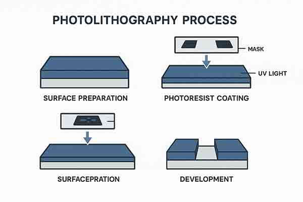
Typical Photolithography Process Steps
-
Wafer cleaning — Particles, organic contaminants, moisture, and process residues are removed from
the wafer surface.
-
Dehydration bake — The substrate is heated to remove adsorbed moisture that could reduce
photoresist adhesion.
-
Surface preparation — An adhesion promoter such as HMDS may be applied to improve bonding between
the substrate and photoresist.
-
Photoresist spin coating — Liquid photoresist is dispensed and spun across the wafer to create a
controlled, uniform film.
-
Soft bake — Residual solvent is removed and the coated resist is stabilized before exposure.
-
Mask alignment — A photomask is aligned with the wafer using a mask aligner or lithography stepper.
-
UV exposure — Ultraviolet light changes the chemical solubility of selected regions of the
photoresist.
-
Post-exposure bake — Some resist systems require additional heating to complete the
photo-induced chemical reaction.
-
Development — The soluble areas of the resist are removed to reveal the desired pattern.
-
Pattern transfer — The developed pattern is transferred into the underlying layer using
wet etching,
plasma etching,
deep reactive ion etching (DRIE),
ion implantation, lift-off, or thin-film deposition.
-
Photoresist removal — The remaining resist is stripped after the pattern-transfer process is
complete.
Positive vs. Negative Photoresist
The choice between positive and negative photoresist depends on feature size, resist thickness, exposure wavelength,
aspect ratio, etch resistance, and the final device structure.
| Property |
Positive Photoresist |
Negative Photoresist |
| Exposure behavior |
Exposed regions become soluble in developer |
Exposed regions cross-link and remain after development |
| Resolution |
Typically preferred for fine features |
Commonly used for thicker or high-aspect-ratio structures |
| Common applications |
Integrated circuits, fine metal patterns, semiconductor devices |
MEMS, microfluidic molds, thick structures, electroplating molds |
| Example |
Standard positive-tone optical resist |
SU-8 photoresist |
How to Select a Wafer for Photolithography
The best photolithography substrate depends on the lithography tool, photoresist, exposure wavelength, device design,
thermal budget, etch chemistry, and final application. Important wafer specifications include:
- Substrate material — Silicon, SOI, glass, quartz, fused silica, sapphire, metal, or polymer.
- Wafer diameter — Common research sizes include 2 inch, 3 inch, 4 inch, 6 inch, and 8 inch.
- Crystal orientation — Silicon wafers are commonly supplied in <100> or <111> orientation.
- Dopant and resistivity — P-type, N-type, undoped, low-resistivity, or high-resistivity material.
- Surface polish — Single-side polished (SSP) or double-side polished (DSP).
- Wafer flatness — Bow, warp, total thickness variation, and surface roughness affect resist uniformity and focus.
- Film coatings — Thermal oxide, silicon nitride, metals, dielectric films, or deposited thin films.
- Etch compatibility — Substrate selection should account for wet etching, RIE, DRIE, KOH, HF, or plasma processing.
Common Substrates Used for Photolithography
| Substrate |
Advantages |
Typical Applications |
|
Silicon wafers
|
Excellent flatness, established processing, adjustable conductivity |
Integrated circuits, MEMS, sensors, microelectronics |
|
Thermal oxide silicon
|
High-quality SiO2 dielectric and masking layer |
MOS devices, isolation, hard masks, MEMS |
|
SOI wafers
|
Buried oxide isolation and controlled device-layer thickness |
MEMS, RF devices, integrated photonics, low-power electronics |
|
Glass wafers
|
Optical transparency and compatibility with bonding processes |
Microfluidics, biosensors, lab-on-chip devices |
|
Fused silica
|
High UV transmission, low thermal expansion, chemical stability |
Photomasks, diffractive optics, UV lithography, photonics |
|
Quartz wafers
|
Dimensional stability, piezoelectric behavior, optical transmission |
SAW devices, resonators, sensors, optical components |
|
Sapphire wafers
|
Hardness, chemical resistance, transparency, high-temperature stability |
GaN devices, LEDs, optical devices, high-temperature sensors |
| Metal-coated wafers |
Conductive surfaces for patterning, plating, and thermal studies |
Electrodes, interconnects, heat-transfer research, sensors |
Applications of Photolithography
Photolithography supports micro- and nanoscale patterning across semiconductor, optical, biomedical, and
microelectromechanical device fabrication.
Photolithography Equipment Required
A university laboratory requested assistance sourcing equipment to establish a complete educational
semiconductor fabrication laboratory.
The requested laboratory equipment included:
- Tube furnace for thermal oxidation, diffusion, and annealing.
- Spin coater for uniform photoresist deposition.
- Hot plates or bake ovens for dehydration, soft bake, and post-exposure bake.
- Mask aligner or lithography exposure system.
-
PVD and CVD deposition systems
for metals and dielectric films.
- Wet benches for cleaning, developing, stripping, and chemical etching.
- Reactive ion etching or plasma etching equipment.
- Wire bonder for integrated circuit and sensor packaging.
- Wafer handling tools, vacuum wands, tweezers, and storage containers.
- Optical microscopes, profilometers, and inspection equipment.
- Packaging materials, conductive adhesives, and encapsulation resins.
The goal was to establish an educational cleanroom capable of supporting wafer cleaning, oxidation,
photolithography, deposition, etching, inspection, dicing, wire bonding, and device packaging.
Reference #316902 for specifications and pricing.
Need Photolithography Substrates?
UniversityWafer supplies
silicon wafers,
thermal oxide wafers,
silicon nitride wafers,
SOI wafers,
glass substrates,
fused silica,
quartz wafers,
and
sapphire wafers
for photolithography, microfabrication, MEMS, CMOS, photonics, microfluidics, and semiconductor research.
Custom wafer diameters, crystal orientations, resistivities, thicknesses, surface finishes, oxide layers,
nitride coatings, metal films, and research quantities are available upon request.
Related Photolithography and Microfabrication Resources
