I am a MEMS project manager of IC Design Research and Education Center (ICDREC),. We are doing projects on MEMS sensors Fabrication and we need to buy materials from your company (please see the attached file).
Could you please give us a quotation and delivery cost so that we can order your product. We are looking forward to hear from you soon.
MEMS Sensor IC Design and Fabrication
A MEMS project manager needed a quote for the following.
Reference #11910 for specs and pricing.
Get Your Quote FAST! Or, Buy Online and Start Researching Today!
How Do You Become a IC Designer?
Let’s break it down into what you need to get into IC design, depending on where you’re coming from. Whether you're a student, transitioning engineer, or just curious, here’s a step-by-step roadmap.
🎯 Step 1: Choose Your Path
There are several specializations in IC design. Start by identifying which track suits you best:
| Track | Best For | Core Skills |
|---|---|---|
| 🔢 Digital IC Design | EE, CS majors | RTL (Verilog/VHDL), Logic design |
| ⚡ Analog IC Design | EE, Physics | Transistor theory, SPICE, layout |
| 🎛️ Mixed-Signal Design | EE | Combines analog + digital |
| 🧱 Physical Design | CS/EE | VLSI, layout tools |
| ✅ Verification | CS-heavy | Testbenches, SystemVerilog/UVM |
| 🧪 DFT/Test | EE | Scan chains, test coverage |
| 🛠️ EDA Tools | CS, Math | Programming, algorithms |
🧑🎓 Step 2: Educational Requirements
-
Bachelor’s Degree in:
-
Electrical Engineering (most common)
-
Computer Engineering
-
Computer Science (for EDA/Verification roles)
-
Physics (sometimes for analog or research roles)
-
-
Master’s Degree (optional but helpful):
-
Makes it easier to land front-end (RTL) or analog design roles at big companies.
-
🛠️ Step 3: Learn the Core Skills
Here’s what you need to study, broken down by track:
🔢 Digital IC Design
-
Verilog / VHDL
-
Digital logic (flip-flops, FSMs, pipelining)
-
Computer architecture (basic CPU/GPU design)
-
Synthesis & Timing (setup/hold time, STA)
-
Tools to learn:
-
Synopsys Design Compiler
-
Cadence Genus
-
ModelSim / VCS
-
⚡ Analog IC Design
-
MOSFET/BJT circuit design
-
Operational amplifiers
-
Matching, noise, layout techniques
-
SPICE simulations
-
Tools:
-
Cadence Virtuoso
-
Spectre / HSPICE
-
🧱 Physical Design
-
VLSI layout
-
Clock tree, IR drop, congestion
-
Static timing analysis
-
Tools:
-
Cadence Innovus
-
Synopsys ICC2
-
✅ Verification
-
SystemVerilog
-
UVM (Universal Verification Methodology)
-
Assertion-based verification
-
Tools:
-
QuestaSim
-
Synopsys VCS
-
JasperGold (formal)
-
🧪 Design for Test (DFT)
-
Scan chains
-
BIST (Built-in self-test)
-
Fault models (stuck-at, transition faults)
-
Tools:
-
Mentor Tessent
-
Synopsys DFT Compiler
-
🛠️ EDA Tool Development
-
Programming: C++, Python, Tcl
-
Algorithms: Graph theory, SAT solvers, logic optimization
-
Linux tools & scripting
💻 Step 4: Get Hands-On Experience
You can’t learn IC design without actual tool use or projects.
-
University labs/projects: If you're in school, use your labs wisely.
-
Online courses: Platforms like:
-
Coursera – Digital circuits, FPGA courses
-
[edX MITx or IIT Bombay] – Analog and digital IC design
-
Open-source tools to try at home:
📄 Step 5: Build a Resume/Portfolio
-
Do projects: RTL design, simulation, layout, etc.
-
Use GitHub to show your work.
-
Do an internship or contribute to open-source (Google’s OpenROAD, for example).
🚪 Step 6: Apply to Jobs or Internships
-
Big players: Intel, AMD, Nvidia, Qualcomm, Broadcom, Apple, Synopsys, Cadence, etc.
-
Startups: Chiplet and AI ASIC startups are booming.
-
Foundries & fabs: TSMC, GlobalFoundries, SkyWater.
Job Titles to search for:
-
“RTL Design Engineer”
-
“Digital Design Engineer”
-
“Analog IC Design Engineer”
-
“Physical Design Engineer”
-
“Verification Engineer”
-
“DFT Engineer”
-
“EDA Software Engineer”
What is IC Design?
Integrated Circuit (IC) design is the process of creating microelectronic circuits—essentially the "brains" inside electronic devices—on a semiconductor substrate, usually silicon. This includes everything from designing the logic of a microprocessor to laying out analog circuits for amplifiers or sensors.
🧠 What is IC Design?
IC design involves conceptualizing, simulating, verifying, and laying out the microscopic components of a chip such as:
-
Transistors
-
Capacitors
-
Resistors
-
Interconnects (wiring)
These components are fabricated together on a single piece of semiconductor material, forming what's called an integrated circuit.
👷♂️ Key Job Titles in IC Design
Here’s a breakdown of common job roles in the field:
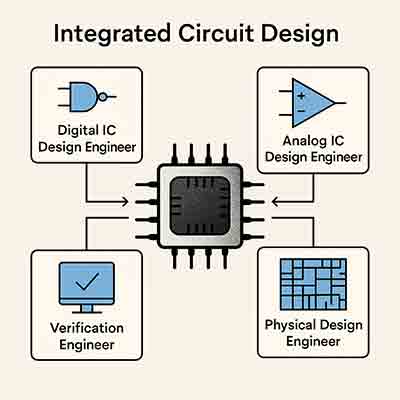
1. Digital IC Design Engineer
-
Focus: Design of digital logic circuits (e.g., CPUs, GPUs, ASICs).
-
Tools: Verilog/VHDL, SystemVerilog, RTL design, synthesis tools like Synopsys or Cadence.
-
Tasks: Design of logic blocks, clock gating, power optimization, verification support.
2. Analog IC Design Engineer
-
Focus: Circuits handling real-world signals (e.g., amplifiers, ADCs, DACs, PLLs).
-
Tools: SPICE simulation, Cadence Virtuoso.
-
Tasks: Transistor-level design, layout, matching, and noise/power optimization.
3. Mixed-Signal IC Designer
-
Focus: Combines analog and digital (e.g., data converters, RF front ends).
-
Tasks: Interface circuits, analog-digital boundary design.
4. Physical Design Engineer
-
Focus: Back-end design – placing and routing the chip layout.
-
Tools: Cadence Innovus, Synopsys ICC2.
-
Tasks: Floorplanning, placement, routing, timing closure, power planning.
5. Verification Engineer
-
Focus: Ensures chip designs work as intended before fabrication.
-
Tools: SystemVerilog, UVM, formal verification tools.
-
Tasks: Create testbenches, simulate and debug RTL designs.
6. DFT (Design for Test) Engineer
-
Focus: Insert and verify test structures like scan chains and BIST (built-in self-test).
-
Tools: Tessent (Mentor), Synopsys DFT Compiler.
7. Packaging Engineer
-
Focus: Physical encapsulation and I/O design of chips.
-
Tasks: Wire bonding, flip-chip design, thermal/electrical modeling.
8. EDA Tool Developer
-
Focus: Develop software tools used by all the above engineers.
-
Background: Strong CS/math skills; may work at Cadence, Synopsys, or Mentor.
🧪 What Substrates Are Used?
The substrate is the base material where all the devices are built. Here's what’s common:
| Substrate | Use Case |
|---|---|
| Silicon (Si) | Standard for most ICs (digital & analog) |
| Silicon-on-Insulator (SOI) | High-speed, low-power, RF & radiation-hardened ICs |
| GaAs, GaN | High-frequency RF or power applications |
| Sapphire | RF front ends, optics, radiation resistance |
| Silicon Carbide (SiC) | Power electronics, high voltage |
| Germanium (Ge) | Often used with Si for high-mobility devices |
| Compound semiconductors | Specialized sensors or optoelectronics |
🏭 IC Design Process: Overview
-
Specification – What the chip is supposed to do.

-
Architecture – Block-level design.
-
RTL Design – Logic description (mostly digital).
-
Simulation & Verification – Ensure correctness.
-
Synthesis & Layout – Transform design into geometry.
-
DFT Insertion
-
Tape-out – Final design sent to fabrication.
-
Fabrication – Made at a foundry (e.g., TSMC, Intel).
-
Testing – Wafer probe, packaging, final test.
Integrated Circuit Design Work Flow
Here is a detailed look at the IC design flow—from an idea in someone’s head to a chip running in your smartphone. It’s a mix of engineering, science, and art, really.
🛠️ Step-by-Step IC Design Flow
1. Specification Phase
-
Goal: Define what the chip will do.
-
Inputs: Market needs, product goals, power, area, and performance targets.
-
Output: A written spec detailing features (e.g., "A 32-bit RISC-V core with 1GHz clock speed, <1W power").
2. Architecture Design
-
Goal: Design the block-level structure of the chip.
-
What Happens:
-
Partition the design into functional blocks (CPU core, memory, I/O, etc.)
-
Choose data paths, control logic, memory architecture
-
Early performance & power estimation
-
3. RTL Design (Register Transfer Level)
-
Tools: Verilog, VHDL
-
Goal: Code the chip logic at a high abstraction.
-
Example:
verilogalways @(posedge clk) begin if (reset) counter <= 0; else counter <= counter + 1; end -
Engineers: Digital Design Engineers
4. Functional Verification
-
Goal: Make sure the RTL does what it’s supposed to.
-
Tools: SystemVerilog, UVM, Questa, VCS
-
Methods: Simulation, testbenches, assertions, coverage
-
Bonus: Formal verification (mathematical proof of correctness)
5. Synthesis
-
Goal: Convert RTL to gate-level (real logic gates)
-
Tools: Synopsys Design Compiler, Cadence Genus
-
Output: Netlist (standard cells mapped to a tech library)
6. Place and Route (Physical Design)
-
Goal: Physically lay out the gates and wires
-
Sub-steps:
-
Floorplanning: Place large blocks (memory, I/O, etc.)
-
Placement: Place logic gates
-
Clock Tree Synthesis: Balance timing across chip
-
Routing: Connect everything with metal layers
-
-
Tool: Cadence Innovus, Synopsys ICC
7. Timing Analysis & Optimization
-
Goal: Ensure signal timing meets clock constraints
-
Tools: PrimeTime, Tempus
-
Checks:
-
Setup and hold time violations
-
Slack analysis
-
IR drop, signal integrity
-
8. DFT (Design for Test)
-
Goal: Insert test structures to allow chip testing after fab
-
Tools: Mentor Tessent, Synopsys DFT Compiler
-
Includes: Scan chains, BIST, boundary scan
9. Tape-out
-
Goal: Create the final files (GDSII or OASIS) sent to a foundry like TSMC, Intel, or GlobalFoundries.
-
This is the big milestone before fabrication.
10. Fabrication
-
Substrate Used: Usually silicon wafers, sometimes SOI or GaAs.
-
Process: Optical lithography, ion implantation, etching, CMP, etc.
-
Output: Bare silicon dies on a wafer.
11. Packaging and Testing
-
Die Packaging: Into a chip (e.g., BGA, QFN, Flip-Chip)
-
Testing:
-
Wafer-level test (probe)
-
Post-package functional test
-
Burn-in testing for reliability
-
🚀 After All That… It Ships!
Now your design becomes part of:
-
A phone
-
A car
-
A data center server
-
A satellite
-
Or something in your microwave or coffee machine 😄
🧑💼 Who Does What Again?
| Phase | Engineer Type |
|---|---|
| Spec & Arch | Systems Architect |
| RTL & Logic | Digital Design Engineer |
| Verification | Verification Engineer |
| Synthesis | Logic/Front-End Engineer |
| Layout | Physical Design Engineer |
| Test Design | DFT Engineer |
| EDA Tools | EDA Software Engineer |
| Analog | Analog IC Designer |
| Packaging | Packaging Engineer |
| Product Test | Product/Test Engineer |
What is Photonic Integrated Circuit Design?
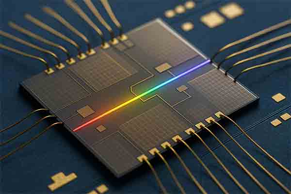
Photonic Integrated Circuit (PIC) design is the process of creating chips that use light (photons) instead of, or alongside, electricity (electrons) to perform functions like data transmission, signal processing, or sensing. It’s like designing an electronic chip (IC), but for optical components.

🔍 What Is a PIC?
A Photonic Integrated Circuit integrates multiple optical components — such as lasers, modulators, detectors, and waveguides — onto a single chip, much like an electronic IC integrates transistors, capacitors, and resistors.
🧩 Key Components on a PIC:
| Optical Element | Function |
|---|---|
| Waveguides | Channels that guide light (like wires for light) |
| Modulators | Encode information onto light |
| Photodetectors | Convert light into electrical signals |
| Lasers | Light sources |
| Splitters/Combiners | Divide or combine optical signals |
| Filters | Select specific wavelengths |
🛠️ PIC Design Workflow:
-
System Specification
Define optical/electrical performance targets, e.g., wavelength range, data rate. -
Component Selection
Choose or design lasers, waveguides, detectors, etc., depending on application (telecom, lidar, biosensors, etc.). -
Layout Design
Use specialized EDA tools like Luceda, Synopsys OptoDesigner, or Photon Design to build the chip layout. -
Simulation & Modeling
Simulate optical behavior using tools like Lumerical to verify losses, coupling, reflection, and signal integrity. -
Fabrication
Chips are fabricated on platforms like Silicon Photonics (SiPh), Indium Phosphide (InP), or Silicon Nitride (SiN). -
Testing & Packaging
Align optical fibers, test insertion loss, bandwidth, and thermal stability.
🔬 Applications of PICs:
-
📡 Telecommunications / Datacom – High-speed optical transceivers
-
💻 AI & HPC – Optical interconnects for faster data transfer
-
🚘 Lidar – For autonomous vehicle sensing
-
🧪 Biosensing – Label-free detection of biomolecules
-
⚛️ Quantum Photonics – Integrated platforms for qubit communication
🧠 Who Designs PICs?
| Role | Description |
|---|---|
| Photonic IC Designer | Designs layout and simulates optical components |
| Process Engineer | Oversees fabrication and tolerances |
| Test Engineer | Develops test protocols for optical performance |
| Packaging Engineer | Works on integrating fiber and electrical interconnects |
