Epitaxial Silicon Wafers for University Research
An electrical engineering professor requested a quote for the following epi silicon wafers:
I am looking at your inventory for epitaxial Silicon and came  across these items. Are they still available and what is the price for a few wafers? I probably only need 1 or two types of wafers each one or two wafers to start my experiment and may come back to purchase the rest of the batch if they work for me.
Question:
Could you tell me what is the difference between P/E and P/EOx surfaces?
Answer:
P/E means that the substrate wafers were one-side-polished - front-side polished and back-side Alkaline-etched. The Epi layer was grown on the polished side. After Epi deposition, the back-side remains Alkaline-etched with some areas around the edges where some Epi gasses deposited on the back-side.
Where one wants to avoid evaporation of dopants from the substrate back-side during Epi deposition, it is common to seal wafer back-side with a layer of SiO2 deposited on etched back-side. Such substrates are denoted as P/EOx. This is commonly done when the substrates are heavily doped or when one wants to achieve very high resistivity in the Epi layer. After Epi deposition, the back-side is a film of Silicon dioxide, with possible deposition from Epi gasses around the edges.
Refernce #251939 for specs and pricing.
Get Your Quote FAST! Or, Buy Online and Start Researching Today!
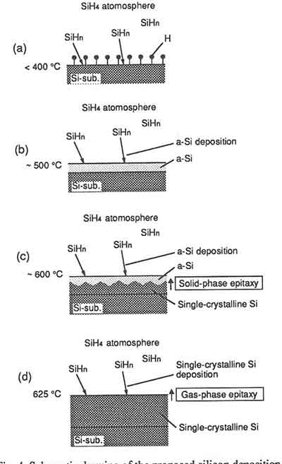
Epitaxial Deposition
Epitaxy is the depositing of a crystalline layer over a crystalline-based semiconductor substrate or surface.
The epitaxy process is used to form epitaxial devices on silicon wafers, which are thin nanolayers of semiconductor crystals. By combining different semiconductor materials and dopants in an epi wafer helps determine the performance capabilities of photonics and radio-frequency (RF) semiconductor components.
UniversityWafer, Inc. epitaxial silicon wafers are perfect for use in forming these types of devices. We have the tools and experience to deposit the layer uniformly, so you can be sure your device will perform at its best.
What is The Main Difference Between Epi-Ready and Regular Silicon Wafer?
Researcher asks:
I am wondering whats the main difference between your epi-ready wafer and regular Si wafer. Does epi-ready wafer has better surface roughness? I need to grow sub-5 nm film on Si and I need a very flat surface. Do you have any recommendations about such DSP Si wafer?
Our Reply:
Unless noted, all of our polished wafers are Epi-Ready on the front side.
Epitaxy Video
What is The Silicon Epitaxial Growth Rate Substrate Ori
 An epitaxial growth rate is a measurement of the amount of growth that occurs on a substrate. It is a determinant of the stability of a device, as it is used to support the manufacturing process. This growth rate depends on the crystal Ori of the substrate. However, it can be affected by external factors. Here, we discuss the limiting factor in the process and describe its quantitative behavior. This article discusses the limiting factor and discusses how the epitaxial structure influences the growth rate.
When the crystals are positioned at the interface between an amorphous layer and a solid phase, the growth rate increases as the Si layers grow. This growth rate is called the critical thickness. As a result, the critical thickness of epitaxial films is reduced and the growth rate is accelerated. In addition, the crystal Ori is a key factor in determining the growth rate of epitaxial films. If the growth rate is slow, it is because the epitaxial layers are too thin.
An epitaxial growth rate of a material can be calculated if the thickness of the film is known beforehand. It is calculated by dividing the number of epitaxial layers by the thickness of the outermost layer. A higher rate of growth is a good indication that the substrate is growing properly. This is because it means that the crystals are positioned in the correct manner. It is also an indication of the growth rate of the material.
The structure of an epitaxial film is a complicated structure. A crystal is composed of multiple layers. The top layer is generally higher than the bottom layer, and the bottom layer is lower than the top. This structure is often a result of strain relief. The surface of a semiconductor can be oriented in either direction. This process is called a hydrothermal process. This technique involves hydrothermal fusion. The temperature of a solid is a major factor in the growth rate of a thin film.
The epitaxial growth rate can be measured using a microscope to see the thickness of the silicon layer. In contrast, the thickness of a silicon chip can be measured using the method that is best suited for the process. The wavelength of the light is important to determine the size of the crystalline layers. The wavelength of the laser varies between different semiconductors. It is possible to measure the thickness in any region of the wafer, but it is crucial to check the optimum temperature and gas distribution.
The epitaxial growth rate of silicon and germanium crystals is dependent on crystal orientation. The (100) surface would have higher epitaxial growth rate than the (110) surface. The same principle holds true for the other crystal Oris. The same is true for the substrate's Ori. In the semiconductor industry, epitaxial growth is essential for the semiconductor industry. While it may be the most straightforward technique for producing thin-films, it is essential to develop new methods for improving the production process.
Various methods have been developed for silicon epitaxial growth. For example, the SiHCl 3 H 2 system can be used to control the growth rate of silicon. The chemical reaction rate can also be controlled using an in situ approach. During a single-wafer reactor, the two types of electrodes must be separated by a grain-to-grain boundary. When the seed layer is flat, the growth can be controlled.
In this method, the seed crystal is deposited on a substrate. In this process, the crystal grows on the substrate below the melting point. The epitaxial process is a method of growth wherein the crystal is grown below its melting point. It is also possible to add different proportions of impurities. The method can be controlled using an evaporation method. When using an evaporation method, it is necessary to use a high-temperature chamber.
Epitaxial growth of a III-V layer on a silicon wafer is a classic approach. It is a method of forming thin films of semiconductor material by sputtering on a silicon wafer. The process involves the growth of a thin layer of Gallium Arsenide (GaAs) on a silicon substrate. But the epitaxial growth of GaAs is also possible on silicon. In contrast, the epitaxially formed GaAs layer on a silicon wafer is not a scalable process.
What is Silicon Epitaxy?
You have probably been wondering: What is silicon epitaxy? What is the process? What is its purpose? The process is a type of semiconductor manufacturing in which a layer of atoms is transferred onto a substrate using a laser. The resulting layer of material is transparent, which means that it can be used to create a variety of products. It is also referred to as a "silicon film," which is deposited onto a surface.
Silicon epitaxy is a method of chemical vapor deposition. The process is complicated and requires multiple simultaneous chemical reactions to occur. The amount of energy required to grow the epitaxial layer depends on the sources of chemicals and the amount of hydrogen used as a carrier gas. Once the layers are formed, they can be patterned into whatever shape the manufacturer wants. The process is similar to the process of forming nanometer-scale crystals, but it has a limited number of applications.
Silicon epitaxy involves growth of a thin film on a substrate wafer. The substrate's crystalline lattice must align with the epitaxial film's lattice. When using this method, a semiconductor film is said to be homoepitaxy if it is made of the same material as the substrate, while heteroepitaxy is used when the layer is made of a different material.
Unlike crystal growth, silicon epitaxy involves a complex chemical reaction. In the semiconductor industry, silicon epitaxy is used to grow thin layers of semiconductor material, which are used in integrated circuits. Moreover, it is also used to make optoelectronic devices. This process is also used to repair damaged or faulty crystals. Once epitaxial layers are formed, they grow in size. However, there are several complications with this process.
Silicon epitaxy is not a straightforward process. Instead, it involves a series of chemical reactions that occur simultaneously. These chemical reactions control the growth rate of the epitaxial layer. The growth rate of the epitaxial layer depends on a number of factors, including the chemical sources and the mole fraction of the reactants. A silicon layer is a single crystal, so a thin film must be made of the same material as the substrate.
Unlike epitaxy, silicon epitaxy is a complex process that involves a series of chemical reactions that occur simultaneously. During the growth of an epitaxial layer, the chemical substances are deposited on top of a layer of another crystal. As a result, they grow in layers. The process is also called as'stacking'. A silicon-based device can be made in two ways, with each layer formed in two different directions.
While it sounds simple, silicon epitaxy is a complex process. Several chemical reactions take place at the same time. The growth rate of an epitaxial layer will depend on the mole fraction of the reactants, the deposition temperature, and the chemical sources. If the growth rate is too slow, the layers may not grow properly. The growth rate of the epitaxial layer can be reduced by protecting the surfaces during handling.
In contrast, the process is used to grow silicon-based semiconductors. The process is particularly important for compound semiconductors, such as gallium arsenide. During the growth process, the semiconductors are exposed to many unwanted compounds. The process is also crucial for creating crystal-damaged silicon. It is not only used to make silicon-based devices, but it is also used to grow various compound materials, including polycrystalline films.
Silicon epitaxy is not a simple process. It is a complex process that involves the simultaneous growth of multiple layers of semiconductor materials on a substrate. The crystalline layers are created in the epitaxial layer. There are two kinds of epitaxial layer: a homoepitaxy and a heteroepitaxy. In either case, the two types of growth are the same. The latter is a type of vapor phase of epitaxy.
The process of silicon epitaxy is a very complex one. A silicon epitaxial wafer is a single-crystalline silicon wafer. It is made up of many atoms, which can be heteroepitaxy or homoepitaxy. For example, a noncrystalline film can be formed on top of a crystalline layer. These layers are the same atoms that make up the silicon layers.
What is Epitaxially?
Epitaxy - The Growth of Thin Films of Semiconductor Material Epitaxially
The growth of a thin film of a material can be monitored by diffracted light. The film thickness is equal to the total thickness of the epitaxial layers grown on the substrate. The d'' value represents the average thickness of the epitaxial layer. When the d'' value is less than 0.7, then the process is called "short-path". This method is widely used in the semiconductor industry for a wide range of applications.
The term epitaxy derives from the Greek prefix "epi" meaning "over" and taxis, "arrangement." During the process, crystalline thin films are formed, often in multiple distinct layers. In some instances, the growth layers are made from the same material while in other cases they are made from different materials. This can lead to heteroepitaxy. In general, epitaxy is the preferred method for making devices and films.
Epitaxial growth is a technique used in the semiconductor industry to grow thin films of semiconductor material. The film must have a lattice aligned with that of the substrate. This is called homoepitaxy. In some cases, the substrate is made from the same semiconductor compound as the film, while in others it is made from a different one. The growth rates of epitaxial films differ from single-crystal films.
The growth rate of silicon and germanium crystals depends on their Ori. A higher rate of epitaxial growth is obtained on the surface (100) than on the surface (110). The Ori of the substrate also affects the epitaxial growth rate. These factors make epitaxial film production an essential part of the semiconductor industry. However, it does not mean that this technique is easy to perfect. In fact, it is the simplest and most cost-effective technique for producing thin films. In fact, it is one of the most popular techniques used in the semiconductor industry.
Unlike in other processes, epitaxial growth is a more complex process. In general, the substrate is flat and the layer is made from a layer of thin films. The two layers must be oriented in such a way that they do not interfere with each other and form a stable device. Further, the substrate must be orientated in the x-ray plane. This is the most common process in semiconductor manufacturing.
A thin film can be grown epitaxially on many different substrates. The surface is a substrate made of rock salt. The interface is very flat and can be easily removed from the substrate. In this way, the epitaxial growth process has a variety of advantages. There are two types of crystallization: the heteroepitaxy and homoepitaxy of the material. Once the layer has grown epitaxially, it can be patterned to grow onto a polycrystalline material.
The growth of a material on a substrate epitaxially is a common process in the semiconductor industry. It is important for semiconductors to grow on a substrate of the same type as its substrate. In this way, the layers can be layered, and the resulting layer can be patterned into many shapes. A high-quality film can be printed with an excellent image quality. The final product will be a highly stable device.
What are the Steps for Epitaxial Growth?
The first step in the growth of a material epitaxially is to measure the bond strengths of the atomic layers. During the process, the electrodes are exposed to a wavelength of light. This signal allows scientists to measure the thickness of the epitaxial layer and its atomic layer. During the growth process, it is critical to monitor the diffraction of light. A large amount of light will prevent growth of a material.
A complex compound grows epitaxially on a single crystal. The substrate plane is a plane with a symmetry. The heavy atoms show up as white dots in a square array. The growth process is more complex than a monolayer film. A film with an epitaxial growth is easier to interpret than a film of the same type. It is important to know the properties of the material you're using before applying this technique.
The process of epitaxial growth refers to the deposition of a crystalline overlayer on a crystalline substrate. The process can be used in the fabrication of thin-film lasers, transistors, and diodes. It is a highly accurate method and can be used to produce nanoscale layers of any material. It is often used in the electronics industry. This method is useful in making high-performance thin-film semiconductors.
What are Silicon Epitaxial Applications?
Silicon (Si) Epitaxial Wafers are ubiquitous in fabricating semiconductor devices for consumer, industrial, military and space electronics.
UniversityWafer, Inc. provides the silicon wafer specs rquired for the followingl microelectronics applications:
Diodes
Schottky diodes
Ultra-fast diodes
Zener diodes
PIN diodes
Transient Voltage Suppressors (TVS)
and other
Transistors
Power IGBT
Power DMOS
MOSFET
Medium power
Small-signal
and other
Integrated Circuits
Bipolar ICs
EEPROM
Amplifiers
Microprocessors
Microcontrollers
RFID
and other
QW Structures Epitaxial Wafers
A Semiconductor Project Manager requested a quote for their research.
We are interested in new suppliers to provide green wavelength (~525nm) LED structures or QW structures epitaxial wafers on 2”, 3” or 4” wafers.
Could you please provide a quote and specification sheet for your green wavelength structures? We can provide more information for the quote if you need it. We look forward to hearing back from you.
Could you also provide performance specification sheets for the structures and prices? We would like to know the:
- Emission wavelength
- Emission FWHM
- IQE or EQE
And if available
- P-type carrier concentration
- IV device curve
- LI device curve
UniversityWafer, Inc. Quoted:
Our 4" and 6" GaN LED epi wafers are full LED structures,Structure consiting of n-type, QW, and p-type,green light emission (525-550nm) can be provide,Also we can do
upon your request,While our wafers sent out,We will provide the epi grown structures.
Reference #261683 for specs and pricing.
Silicon Epitaxial Substrate and Services
UniversityWafer, Inc. is a leading supplier of Silicon Epitaxial Wafers (epi wafers). Our substrates work great for fabricating high-performance semiconductor devices. We carry stock and can handle custom made epi wafers. Also, we can supply epi wafers (single layer and multilayer) that are used to manufacture a broad range of discrete semiconductors and ICs, including
- Power Mosfets: Power MOSFETs (Metal-Oxide-Semiconductor Field-Effect Transistors) are a type of transistor commonly used in power electronics applications. They are specifically designed to handle high voltage and current levels while offering fast switching speeds, low on-resistance, and efficient performance.
- Bi-polar transistors: Bipolar Junction Transistors (BJTs) are a type of semiconductor device that consists of three layers of doped semiconductor material: an emitter, a base, and a collector. These three layers form two adjacent pn-junctions, giving the BJT its name. There are two types of BJTs: NPN (N-type material is sandwiched between two P-type layers) and PNP (P-type material is sandwiched between two N-type layers).
- Transient-Voltage-Suppression (TVS): Transient Voltage Suppression (TVS) refers to a technique or a family of devices used to protect sensitive electronic circuits from voltage spikes or transient overvoltage events. These events can be caused by various factors, such as electrostatic discharge (ESD), lightning, inductive load switching, or power supply fluctuations. If left unprotected, these voltage spikes can cause damage to electronic components or lead to a complete system failure.
- Zener diodes: A Zener diode is a type of semiconductor diode that is specifically designed to operate in the reverse breakdown region, where it exhibits a well-defined and stable reverse breakdown voltage, also known as the Zener voltage. This characteristic allows Zener diodes to be used as voltage regulators, clippers, and reference elements in various electronic circuits.
- Schottky rectifiers: Schottky rectifiers, also known as Schottky diodes, are a type of semiconductor diode characterized by a metal-semiconductor junction instead of the typical semiconductor-semiconductor junction found in conventional diodes. This metal-semiconductor junction is formed between a metal, such as platinum or tungsten, and a lightly doped n-type semiconductor material, like silicon or gallium arsenide.
- PIN diodes: A PIN diode is a type of semiconductor diode that has a unique structure consisting of three layers: a P-type semiconductor (P), an intrinsic (undoped or very lightly doped) semiconductor (I), and an N-type semiconductor (N). The intrinsic layer is sandwiched between the P and N layers, giving the diode its name: PIN.
- IGBT devices: Insulated Gate Bipolar Transistor (IGBT) devices are a type of power semiconductor device that combines the advantages of both Bipolar Junction Transistors (BJTs) and Metal-Oxide-Semiconductor Field-Effect Transistors (MOSFETs). They are widely used in power electronics applications, where they provide efficient switching and the ability to handle high voltages and currents.
- Linear IC's: Linear Integrated Circuits (ICs) are a type of electronic component that consist of analog circuits fabricated on a single semiconductor chip. These circuits perform linear (or continuous) signal processing functions, as opposed to digital ICs, which operate with discrete signals, such as binary logic levels.
- MEMS devices: Micro-Electro-Mechanical Systems (MEMS) are miniaturized devices or systems that combine electrical and mechanical components on a microscopic scale. They are typically fabricated using semiconductor manufacturing techniques, such as photolithography and etching, which enable the creation of complex structures and moving parts at the micro- or even nanometer scale.
UniversityWafer, Inc. and our partner’s epi substrates range from diced pieces to 300mm diameters. They are fabricated in single-wafer reactors and batch-processed reactors.
Epitaxial layers can be doped with phosphorus and boron range from less than 1 ohm-cm to over 50 ohm-cm. Our Arsenic-doped epi layers provide very stable doping profile placement during subsequent high-temperature processing by the device maker.
Epi Layers of any doping type (phosphorus, boron, or arsenic) can be produced as thin as 2 µm up to a maximum thickness of about 150 µm.
We focus on preparing silicon wafer surface to have high-quality defect-free layers. We offer all wafer types and dopants from less than 1 ohm-cm and have the ability to work with red phosphorus doped wafers if you device requires very low forward voltages for Schottky rectifier specifications.
The silicon wafer’s backsides can be provided with many customized options, including:
- Soft backside damage
- Hard backside damage,
- Backside sealed with polysilicon in situ during reactor growth
- Low-Temperature Oxide (LTO).
- Advanced backside finishes are available, which include hard backside damage plus LTO or multilayers of polysilicon + LTO.
Backside seals provide extrinsic impurity gettering for critical yield enhancement and dramatically reduce the substrate’s dopant auto-doping effect from affecting the epi layer resistivity profile.
The quality control of epi wafers follows SEMI Standards and ASTM standards.
The following methods and equipment accomplish measurements on finished epi lots of thickness and resistivity parameters:
- Thickness measurements of epi layers by FTIR method using Biorad tools.
- Resistivity measurements by C-V mercury and/or 4-point probe.
- Resistivity measurements by advanced photo-voltage tool, which is non-contact and non-destructive.
- Spreading Resistance Profile (SRP) giving the resistivity and/or doping concentration profile vertically throughout the epi layer.
Silicon Epi Wafers Sale - Many More Available! Just ask!
We have a large selection of wafers in small and large quantities in stock. Please see below for all diameters.

What is Epitaxial Layer
The process of growing thin layers of crystalline silicon on a substrate is called epitaxial growth. The term epitaxy comes from the Greek prefix epi, meaning "upon or over." In this process, a material is grown in several distinct layers that are then backfilled with a highly doped, void-free material. The growth process results in semiconductors that exhibit high aspect ratios, low HF defects, and high crystal quality.
To create an epitaxial silicon film, a melt is first made. This melt contains molecules from the starting substrate and a low-melting-point metal. The layer is partially dissolved on the surface of the substrate. The heat from the melt causes the surface of the wafer to become partially dissolved, resulting in a layer with high resistivity. The next step of the process involves forming a thin layer of a different type of material.
The second step is the process of forming a semiconductor device. In this step, the first layer is formed. The second layer is then fabricated using a chemical vapor deposition (CVD) process. In a subsequent step, the top portion of the third layer is removed, revealing a buried oxide layer. The third layer is then fabricated by thermal oxidation. The silicon layer has a uniform thickness, which can be better than 5% in very thin SOI wafers.
The process of epitaxial growth involves layering and applying a high-strength alumina to a substrate. The silicon layer is grown at a temperature of 500 degC and the etching solution is a mixture of different compounds. It is possible to design a device with two electrically different components. Some epitaxial layers are oxygen-free, allowing for higher temperatures and reduced stress.
In 1960, a team at Bell Labs led by Henry Theurer and his team added a thin layer of silicon between the collector and base of a transistor. Western Electric then used this technology to produce transistors for electronic telephone switching in the Bell System. The process increased the manufacturing costs, but the improvements in performance made it worthwhile. This method has become the standard for semiconductor fabrication. This technique is widely used for high-frequency electronics, especially in power amplifiers.
This process allows the production of semiconductors from a single molecule of silicon. The method is highly efficient and can be applied to a wide range of materials. The most common substrate is a glass with high-quality silicon. A transparent plastic layer can be formed by combining the layers of silicon to create a more flexible device. A conductive layer will be more efficient than a non-conductive one. This method is the most reliable for high-quality computer chips.
The process uses multiple phases to deposit a layer of silicon. The underlying layers are doped with a compound gas to form the epitaxial layer. The p-type epitaxial layer is the most common type. The p-type layer has a high-quality layer of silicon. It is also a good candidate for solar cell applications. It can be fabricated by a variety of techniques. These methods are widely used in semiconductor industry.
The process is highly reproducible, with a tolerance of +-35 nm. The kinks in the epitaxial layer facilitate the nucleation of another crystalline phase. The process is complex but a single-layer SOI wafer can be manufactured easily. During the growth process, the silicon wafer is bonded to an insulating substrate and the resulting crystals are grown layer by layer in the solid phase.
Epitaxial silicon has a long history. The two types of semiconductors are similar in that the first is silicon-on-silicon, while the second is a polycrystalline polysilicon. The p-n junction in the epitaxial layer is a barrier that prevents a CMOS transistor from latching. However, it is not known whether or not the p-n junctions are isolated by epitaxial silicon.
In epitaxial growth, a first silicon layer is grown that contains a porous layer of silicon. The second layer is bonded to the seed wafer, leaving a porous layer of silicon on the device's surface. This process is identical to the one described in section 7.4, with the exception of the thickness of the first layer. As a result, the epitaxial structure is a double-layered structure.
6" Epitaxial Silicon Wafers
| Item |
Qty in Stock |
Substrate |
EPI |
Comment |
| Size |
Type |
Res Ωcm |
Surf. |
Thick μm |
Type |
Res Ωcm |
| G541 |
150 |
6"Øx675μm |
n- Si:P[100] |
0.001-0.002 |
P/EOx |
0.016 |
n- Si:P |
0.32-0.46 |
n/n+ |
4" Epitaxial Silicon Wafers
| Item |
Qty in Stock |
Substrate |
EPI |
Comment |
| Size |
Type |
Res Ωcm |
Surf. |
Thick μm |
Type |
Res Ωcm |
| D274 |
6 |
4"Øx360μm |
n- Si:Sb[111] |
0.005-0.020 |
P/E |
20 |
n- Si:P |
360 - 440 |
n/n+ |
| E4_151 |
8 |
4"Øx400μm |
p- Si:B[111] |
0.01-0.10 |
P/E |
6.5
22±1.5 |
p- Si:B
p- Si:B |
3.6±10%
300±50 |
P/P/P+ |
| E4_134 |
7 |
4"Øx525μm |
p- Si:B[111] |
0.01-0.02 |
P/E |
8.1±1
6.85±0.75 |
p- Si:B
p- Si:B |
4.5±10%
0.75±0.15 |
P/P/P+ |
| E4_104 |
6 |
4"Øx380μm |
p- Si:B[111] |
0.008-0.020 |
P/EOx |
10.5 |
p- Si:B |
570±10% |
p/p+ |
| E4_22 |
3 |
4"Øx440μm |
p- Si:B[111] |
0.008-0.020 |
P/E |
20 |
p- Si:B |
0.15 ±10% |
P/P+ |
| E4_106 |
4 |
4"Øx440μm |
p- Si:B[111] |
0.008-0.020 |
P/E |
20 |
p- Si:B |
0.25±10% |
P/P+ |
| E4_105 |
7 |
4"Øx525μm |
p- Si:B[111] |
0.001-0.005 |
P/E |
20 |
p- Si:B |
175±10% |
P/P+ |
| E4_26 |
10 |
4"Øx440μm |
p- Si:B[111] |
0.008-0.020 |
P/E |
21 |
p- Si:B |
150 ±10% |
P/P+ |
| E4_107 |
8 |
4"Øx380μm |
p- Si:B[111] |
0.008-0.020 |
P/EOx |
23 |
p- Si:B |
200±10% |
P/P+ |
| E4_108 |
9 |
4"Øx380μm |
p- Si:B[111] |
0.008-0.020 |
P/EOx |
23 |
p- Si:B |
80±10% |
P/P+ |
| E4_42 |
4 |
4"Øx440μm |
p- Si:B[111] |
0.008-0.020 |
P/E |
32 |
p- Si:B |
600 ±10% |
P/P+ |
| E4_109 |
8 |
4"Øx440μm |
p- Si:B[111] |
0.01-0.02 |
P/E |
32.5 |
p- Si:B |
100±10% |
P/P+ |
| E4_21 |
5 |
4"Øx380μm |
p- Si:B[111] |
0.008-0.020 |
P/EOx |
40 |
p- Si:B |
550 ±10% |
P/P+ |
| E4_133 |
3 |
4"Øx525μm |
p- Si:B[111] |
0.01-0.02 |
P/E |
14
10 |
n- Si:P
p- Si:B |
2.5±0.3
15 |
N/P/P+ |
| E4_135 |
2 |
4"Øx525μm |
p- Si:B[111] |
0.01-0.02 |
P/E |
14
10 |
n- Si:P
p- Si:B |
2.5±10%
9±10% |
n/p/p+ |
| E4_113 |
8 |
4"Øx525μm |
n- Si:As[111] |
0.0010-0.0035 |
P/E |
20
10 |
p- Si:B
n- Si:P |
10±1.5
5.5±0.7 |
P/N/N+ |
| E4_127 |
5 |
4"Øx381μm |
n- Si:As[111] |
0.0010-0.0035 |
P/E |
33
10 |
p- Si:B
n- Si:P |
12±10%
4±10% |
P/N/N+ |
| E4_147 |
9 |
4"Øx525μm |
n- Si:As[111] |
0.0010-0.0035 |
P/E |
33±5
9 |
p- Si:B
n- Si:P |
12±2
4 |
P/N/N+ |
| E4_128 |
6 |
4"Øx525μm |
n- Si:As[111] |
0.0010-0.0035 |
P/E |
37
16.5 |
p- Si:B
n- Si:P |
35±10%
12.5±10% |
P/N/N+ |
| E4_124 |
7 |
4"Øx525μm |
n- Si:As[111] |
0.0010-0.0035 |
P/E |
45
7±1 |
p- Si:B
n- Si:P |
13±10%
12±10% |
P/N/N+ |
| E4_144 |
6 |
4"Øx525μm |
n- Si:As[111] |
0.0010-0.0035 |
P/E |
45
7 |
p- Si:B
n- Si:P |
14.5±10%
12±10% |
P/N/N+ |
| E4_132 |
8 |
4"Øx525μm |
n- Si:As[111] |
0.002-0.005 |
P/E |
88
88 |
p- Si:B
n- Si:P |
80.5±10%
27±10% |
P/N/N+ |
| E4_145 |
7 |
4"Øx380μm |
n- Si:As[111] |
0.002-0.005 |
P/E |
105
26 |
p- Si:B
n- Si:P |
0.0035±10%
5±10% |
P/N/N+ |
| E4_122 |
5 |
4"Øx525μm |
n- Si:As[111] |
0.0010-0.0035 |
P/E |
10.15
6.8±0.8 |
n- Si:P
n- Si:P |
3.8±0.5
0.55±0.15 |
N/N/N+ |
| E4_84 |
9 |
4"Øx380μm |
n- Si:As[111] |
0.004-0.008 |
P/EOx |
16.5 |
n- Si:P |
35 ±10% |
N/N+ |
| E4_143 |
8 |
4"Øx508μm |
n- Si:As[111] |
0.002-0.005 |
P/E |
19±1.3
54.5±3.6 |
n- Si:P
n- Si:P |
25±5
4.4 |
N/N/N+ |
| E4_68 |
9 |
4"Øx380μm |
n- Si:As[111] |
0.001-0.005 |
P/EOx |
20 |
n- Si:P |
270 ±10% |
N/N+ |
| E4_90 |
8 |
4"Øx400μm |
n- Si:As[111] |
0.001-0.005 |
P/E |
20 |
n- Si:P |
0.09 ±10% |
N/N+ |
| E4_10 |
25 |
4"Øx400μm |
n- Si:As[111] |
0.001-0.005 |
P/E |
20 |
n- Si:P |
90±10% |
N/N+ |
| E4_89 |
9 |
4"Øx400μm |
n- Si:As[111] |
0.001-0.005 |
P/E |
20 |
n- Si:P |
0.07 ±10% |
N/N+ |
| E4_91 |
9 |
4"Øx400μm |
n- Si:As[111] |
0.001-0.005 |
P/E |
20 |
n- Si:P |
0.13 ±10% |
N/N+ |
| E4_92 |
11 |
4"Øx400μm |
n- Si:As[111] |
0.001-0.005 |
P/E |
20 |
n- Si:P |
0.15 ±10% |
N/N+ |
| E4_93 |
7 |
4"Øx400μm |
n- Si:As[111] |
0.001-0.005 |
P/E |
20 |
n- Si:P |
0.19 ±10% |
N/N+ |
| E4_30 |
7 |
4"Øx525μm |
n- Si:As[111] |
0.001-0.005 |
P/E |
20 |
n- Si:P |
65 ±10% |
N/N+ |
| E4_116 |
5 |
4"Øx525μm |
n- Si:As[111] |
0.0010-0.0035 |
P/E |
20
10 |
n- Si:P
n- Si:P |
7±10%
2±0.4 |
N/N/N+ |
| E4_69 |
8 |
4"Øx380μm |
n- Si:As[111] |
0.001-0.005 |
P/EOx |
21 |
n- Si:P |
150 ±10% |
N/N+ |
| E4_117 |
11 |
4"Øx525μm |
n- Si:As[111] |
0.0010-0.0035 |
P/E |
22.5
28.5 |
n- Si:P
n- Si:P |
12±10%
2±10% |
N/N/N+ |
| E4_129 |
9 |
4"Øx525μm |
n- Si:As[111] |
0.0010-0.0035 |
P/E |
26
11 |
n- Si:P
n- Si:P |
18±10%
2±10% |
N/N/N+ |
| E4_54 |
9 |
4"Øx525μm |
n- Si:As[111] |
0.001-0.005 |
P/E |
27 |
n- Si:P |
220 ±10% |
N/N+ |
| E4_52 |
15 |
4"Øx525μm |
n- Si:As[111] |
0.001-0.005 |
P/E |
27.5 |
n- Si:P |
>250 |
N/N+ |
| E4_53 |
9 |
4"Øx525μm |
n- Si:As[111] |
0.001-0.005 |
P/E |
28 |
n- Si:P |
165 ±10% |
N/N+ |
| E4_125 |
14 |
4"Øx525μm |
n- Si:As[111] |
0.0010-0.0035 |
P/E |
28
8 - 12 |
n- Si:P
n- Si:P |
11±10%
1 - 3 |
N/N/N+ |
| E4_120 |
19 |
4"Øx525μm |
n- Si:As[111] |
0.0010-0.0035 |
P/E |
28
9 - 11 |
n- Si:P
n- Si:P |
8 - 11
1 - 3 |
N/N/N+ |
| E4_111 |
20 |
4"Øx525μm |
n- Si:As[111] |
0.0010-0.0035 |
P/E |
30
15
5 |
n- Si:P
n- Si:P
n- Si:P |
11±10%
4±10%
1.5±10% |
N/N/N/N+ |
| E4_123 |
10 |
4"Øx525μm |
n- Si:As[111] |
0.0010-0.0035 |
P/E |
39.5
12 |
n- Si:P
n- Si:P |
29±10%
4±10% |
N/N/N+ |
| E4_81 |
20 |
4"Øx380μm |
n- Si:As[111] |
0.004-0.008 |
P/EOx |
41.5 |
n- Si:P |
>300 ±10% |
N/N+ |
| E4_77 |
18 |
4"Øx380μm |
n- Si:As[111] |
0.004-0.008 |
P/EOx |
41.5 |
n- Si:P |
>200 |
N/N+ |
| E4_17 |
2 |
4"Øx380μm |
n- Si:As[111] |
0.004-0.008 |
P/EOx |
43 |
n- Si:P |
600 ±10% |
N/N+ |
| E4_79 |
8 |
4"Øx380μm |
n- Si:As[111] |
0.004-0.008 |
P/EOx |
43 |
n- Si:P |
>200 |
N/N+ |
| E4_16 |
1 |
4"Øx380μm |
n- Si:As[111] |
0.004-0.008 |
P/EOx |
43 |
n- Si:P |
340 ±10% |
N/N+ |
| E4_115 |
6 |
4"Øx525μm |
n- Si:As[111] |
0.0010-0.0035 |
P/E |
50
15 |
n- Si:P
n- Si:P |
36±4
5.4±0.7 |
N/N/N+ |
| E4_24 |
10 |
4"Øx525μm |
n- Si:As[111] |
0.001-0.005 |
P/E |
75 |
n- Si:P |
66 ±10% |
N/N+ |
| E4_59 |
9 |
4"Øx525μm |
n- Si:As[111] |
0.001-0.005 |
P/E |
78 |
n- Si:P |
25 ±10% |
N/N+ |
| E4_5 |
15 |
4"Øx525μm |
n- Si:As[111] |
0.001-0.005 |
P/EOx |
78 |
n- Si:P |
20 ±10% |
N/N+ |
| E4_94 |
5 |
4"Øx525μm |
n- Si:As[111] |
0.001-0.005 |
P/E |
80 |
n- Si:P |
17.5 ±10% |
N/N+ |
| E4_112 |
4 |
4"Øx525μm |
n- Si:As[111] |
0.0010-0.0035 |
P/E |
80
10 |
n- Si:P
n- Si:P |
60±10%
2±1 |
N/N/N+ |
| E4_146 |
7 |
4"Øx525μm |
n- Si:As[111] |
0.0010-0.0035 |
P/E |
80
10 |
n- Si:P
n- Si:P |
70±10%
2±1 |
N/N/N+ |
| E4_137 |
8 |
4"Øx525μm |
n- Si:Sb[111] |
0.008-0.020 |
P/E |
22.5
15 |
p- Si:B
n- Si:P |
15±10%
6±0.9 |
P/N/N+ |
| E4_136 |
7 |
4"Øx525μm |
n- Si:Sb[111] |
0.008-0.020 |
P/E |
38
18 |
p- Si:B
n- Si:P |
55±10%
10±10% |
P/N/N+ |
| E4_9 |
4 |
4"Øx525μm |
n- Si:Sb[111] |
0.005-0.020 |
P/E |
14 |
n- Si:P |
4.25 ±10% |
N/N+ |
| E4_55 |
4 |
4"Øx525μm |
n- Si:Sb[111] |
0.005-0.020 |
P/E |
15 |
n- Si:P |
90 ±10% |
N/N+ |
| E4_27 |
10 |
4"Øx525μm |
n- Si:Sb[111] |
0.005-0.020 |
P/E |
18 |
n- Si:P |
0.25 ±10% |
N/N+ |
| E4_56 |
6 |
4"Øx400μm |
n- Si:Sb[111] |
0.005-0.020 |
P/E |
20 |
n- Si:P |
75 ±10% |
N/N+ |
| E4_57 |
8 |
4"Øx400μm |
n- Si:Sb[111] |
0.005-0.020 |
P/E |
20 |
n- Si:P |
136 ±10% |
N/N+ |
| E4_58 |
3 |
4"Øx400μm |
n- Si:Sb[111] |
0.005-0.020 |
P/E |
20 |
n- Si:P |
101 ±10% |
N/N+ |
| E4_98 |
5 |
4"Øx400μm |
n- Si:Sb[111] |
0.006-0.020 |
P/E |
20 |
n- Si:P |
300±10% |
N/N+ |
| E4_97 |
9 |
4"Øx400μm |
n- Si:Sb[111] |
0.006-0.020 |
P/E |
21 |
n- Si:P |
400±10% |
N/N+ |
| E4_100 |
15 |
4"Øx525μm |
n- Si:Sb[111] |
0.005-0.020 |
P/E |
22.5 |
n- Si:P |
12.5±10% |
N/N+ |
| E4_2 |
16 |
4"Øx400μm |
n- Si:Sb[111] |
0.005-0.020 |
P/E |
25 |
n- Si:P |
0.08 ±10% |
N/N+ |
| E4_14 |
2 |
4"Øx400μm |
n- Si:Sb[111] |
0.005-0.020 |
P/E |
25 |
n- Si:P |
0.04 ±10% |
N/N+ |
| E4_66 |
5 |
4"Øx360μm |
n- Si:Sb[111] |
0.005-0.020 |
P/E |
37.5 |
n- Si:P |
270 ±10% |
N/N+ |
| E4_95 |
10 |
4"Øx400μm |
n- Si:Sb[111] |
0.006-0.020 |
P/E |
37.5 |
n- Si:P |
85±10% |
N/N+ |
| E4_138 |
4 |
4"Øx525μm |
n- Si:Sb[111] |
0.008-0.020 |
P/E |
58
15
5 |
n- Si:P
n- Si:P
n- Si:P |
60±10%
8±10%
3±10% |
N/N/N/N+ |
| E4_148 |
9 |
4"Øx460μm |
n- Si:Sb[111] |
0.007-0.020 |
P/E |
60
20 |
n- Si:P
n- Si:P |
40.5±4.5
10±2 |
N/N/N+ |
| E4_60 |
9 |
4"Øx525μm |
n- Si:Sb[111] |
0.005-0.020 |
P/E |
60 |
n- Si:P |
60 ±10% |
N/N+ |
| E4_12 |
10 |
4"Øx525μm |
n- Si:Sb[111] |
0.005-0.020 |
P/E |
60 |
n- Si:P |
58.75 ±10% |
N/N+ |
| E4_19 |
6 |
4"Øx525μm |
n- Si:Sb[111] |
0.005-0.020 |
P/E |
70 |
n- Si:P |
60 ±10% |
N/N+ |
| E4_61 |
9 |
4"Øx525μm |
n- Si:Sb[111] |
0.005-0.020 |
P/E |
75 |
n- Si:P |
125 ±10% |
N/N+ |
| E4_44 |
6 |
4"Øx525μm |
n- Si:Sb[111] |
0.005-0.020 |
P/E |
100 |
n- Si:P |
420±10% |
N/N+ |
3" Epitaxial Silicon Wafers
| Item |
Qty in Stock |
Substrate |
EPI |
Comment |
| Size |
Type |
Res Ωcm |
Surf. |
Thick μm |
Type |
Res Ωcm |
| K827 |
4 |
3"Øx508μm |
p- Si:B[111] |
0.008-0.020 |
P/E |
12.5
140±10 |
p- Si:B
n- Si:P |
2.35
33.60 |
p+ |
| 8611 |
50 |
3"Øx381μm |
n- Si:As[111-4°] |
0.001-0.005 |
P/E |
5.5 |
n- Si:P |
0.31 - 0.33 |
n/n+ |
| F667 |
120 |
3"Øx525μm |
n- Si:P[111] |
0.001-0.005 |
P/E |
4.5 |
n- Si:P |
1.1 - 1.4 |
n/n+ |
| E3_32 |
18 |
3"Øx381μm |
n- Si:As[111] |
0.001-0.005 |
P/E |
5.5 |
n- Si:P |
1.06±10% |
N/N+ |
| E3_40 |
5 |
3"Øx381μm |
n- Si:As[111] |
0.001-0.005 |
P/E |
11 |
n- Si:P |
17.5±10% |
N/N+ |
| E3_2 |
9 |
3"Øx381μm |
n- Si:As[111] |
0.001-0.005 |
P/E |
12 |
n- Si:P |
16±10% |
N/N+ |
| E3_54 |
8 |
3"Øx381μm |
n- Si:As[111] |
0.001-0.005 |
P/E |
12 |
n- Si:P |
2.1±10% |
N/N+ |
| E3_55 |
12 |
3"Øx381μm |
n- Si:As[111] |
0.001-0.005 |
P/E |
12 |
n- Si:P |
1.7±10% |
N/N+ |
| E3_24 |
18 |
3"Øx381μm |
n- Si:As[111] |
0.001-0.005 |
P/E |
12 |
n- Si:P |
1.3±10% |
N/N+ |
| E3_38 |
15 |
3"Øx381μm |
n- Si:As[111] |
0.001-0.005 |
P/E |
12 |
n- Si:P |
1.3±10% |
N/N+ |
| E3_62 |
14 |
3"Øx381μm |
n- Si:As[111] |
0.001-0.005 |
P/E |
12 |
n- Si:P |
1.8±10% |
N/N+ |
| E3_30 |
15 |
3"Øx381μm |
n- Si:As[111] |
0.001-0.005 |
P/E |
13 |
n- Si:P |
1.35±10% |
N/N+ |
| E3_48 |
9 |
3"Øx381μm |
n- Si:As[111] |
0.001-0.005 |
P/E |
15.5 |
n- Si:P |
9.5±10% |
N/N+ |
| E3_22 |
12 |
3"Øx381μm |
n- Si:As[111] |
0.001-0.005 |
P/E |
15.5 |
n- Si:P |
9.5±10% |
N/N+ |
| E3_42 |
4 |
3"Øx381μm |
n- Si:As[111] |
0.001-0.005 |
P/E |
18 |
n- Si:P |
0.05±10% |
N/N+ |
| E3_3 |
20 |
3"Øx381μm |
n- Si:As[111] |
0.001-0.005 |
P/E |
22 |
n- Si:P |
4.8±10% |
N/N+ |
| E3_5 |
18 |
3"Øx381μm |
n- Si:As[111] |
0.001-0.005 |
P/E |
22 |
n- Si:P |
4±10% |
N/N+ |
| E3_27 |
5 |
3"Øx381μm |
n- Si:As[111] |
0.001-0.005 |
P/E |
22 |
n- Si:P |
4±10% |
N/N+ |
| E3_63 |
20 |
3"Øx381μm |
n- Si:As[111] |
0.001-0.005 |
P/E |
28 |
n- Si:P |
16.5±10% |
N/N+ |
| E3_17 |
6 |
3"Øx381μm |
n- Si:As[111] |
0.001-0.005 |
P/E |
28.5 |
n- Si:P |
4±10% |
N/N+ |
| E3_25 |
9 |
3"Øx381μm |
n- Si:As[111] |
0.001-0.005 |
P/E |
28.5 |
n- Si:P |
20±10% |
N/N+ |
| E3_53 |
8 |
3"Øx381μm |
n- Si:As[111] |
0.001-0.005 |
P/E |
30 |
n- Si:P |
4.5±10% |
N/N+ |
| E3_15 |
15 |
3"Øx355μm |
n- Si:As[111] |
0.001-0.005 |
P/E |
34 |
n- Si:P |
9.5±10% |
N/N+ |
| E3_16 |
15 |
3"Øx355μm |
n- Si:As[111] |
0.001-0.005 |
P/E |
34 |
n- Si:P |
12±10% |
N/N+ |
| E3_51 |
8 |
3"Øx355μm |
n- Si:As[111] |
0.001-0.005 |
P/E |
34 |
n- Si:P |
11±10% |
N/N+ |
| E3_4 |
9 |
3"Øx355μm |
n- Si:As[111] |
0.001-0.005 |
P/E |
36 |
n- Si:P |
4±10% |
N/N+ |
| E3_23 |
5 |
3"Øx381μm |
n- Si:As[111] |
0.001-0.005 |
P/E |
37.5 |
n- Si:P |
0.6±10% |
N/N+ |
| E3_1 |
20 |
3"Øx381μm |
n- Si:As[111] |
0.001-0.005 |
P/E |
41 |
n- Si:P |
25±10% |
N/N+ |
| E3_41 |
9 |
3"Øx381μm |
n- Si:As[111] |
0.001-0.005 |
P/E |
42 |
n- Si:P |
20.5±10% |
N/N+ |
| E3_19 |
18 |
3"Øx381μm |
n- Si:As[111] |
0.001-0.005 |
P/E |
42.5 |
n- Si:P |
17±10% |
N/N+ |
| E3_14 |
8 |
3"Øx355μm |
n- Si:As[111] |
0.001-0.005 |
P/E |
52.5 |
n- Si:P |
12.5±10% |
N/N+ |
| E3_56 |
19 |
3"Øx381μm |
n- Si:As[111] |
0.001-0.005 |
P/E |
56 |
n- Si:P |
12±10% |
N/N+ |
| E3_45 |
8 |
3"Øx508μm |
n- Si:As[111] |
0.001-0.005 |
P/E |
70 |
n- Si:P |
73±10% |
N/N+ |
| E3_33 |
10 |
3"Øx508μm |
n- Si:As[111] |
0.001-0.005 |
P/E |
72 |
n- Si:P |
12.5±10% |
N/N+ |
| E3_7 |
19 |
3"Øx508μm |
n- Si:As[111] |
0.001-0.005 |
P/E |
73 |
n- Si:P |
84±10% |
N/N+ |
| E3_44 |
8 |
3"Øx508μm |
n- Si:As[111] |
0.001-0.005 |
P/E |
75 |
n- Si:P |
13±10% |
N/N+ |
| E3_49 |
18 |
3"Øx508μm |
n- Si:As[111] |
0.001-0.005 |
P/E |
75 |
n- Si:P |
11±10% |
N/N+ |
| E3_12 |
8 |
3"Øx508μm |
n- Si:As[111] |
0.001-0.005 |
P/E |
80 |
n- Si:P |
12±10% |
N/N+ |
| E3_10 |
15 |
3"Øx375μm |
n- Si:As[111] |
0.001-0.005 |
P/E |
85 |
n- Si:P |
22.5 ±10% |
N/N+ |
| E3_34 |
10 |
3"Øx508μm |
n- Si:As[111] |
0.001-0.005 |
P/E |
85 |
n- Si:P |
19.5±10% |
N/N+ |
| E3_20 |
20 |
3"Øx508μm |
n- Si:As[111] |
0.001-0.005 |
P/E |
85 |
n- Si:P |
66±10% |
N/N+ |
| E3_59 |
18 |
3"Øx508μm |
n- Si:As[111] |
0.001-0.005 |
P/E |
90
18 |
n- Si:P
n- Si:P |
41±10%
5±10% |
N/N/N+ |
| E3_43 |
18 |
3"Øx508μm |
n- Si:As[111] |
0.001-0.005 |
P/E |
96 |
n- Si:P |
30±10% |
N/N+ |
| E3_11 |
19 |
3"Øx508μm |
n- Si:As[111] |
0.001-0.005 |
P/E |
100 |
n- Si:P |
16 ±10% |
N/N+ |
| E3_13 |
2 |
3"Øx508μm |
n- Si:As[111] |
0.001-0.005 |
P/E |
100 |
n- Si:P |
12±10% |
N/N+ |
| E3_21 |
10 |
3"Øx508μm |
n- Si:As[111] |
0.001-0.005 |
P/E |
100 |
n- Si:P |
20±10% |
N/N+ |
| E3_8 |
5 |
3"Øx508μm |
n- Si:As[111] |
0.001-0.005 |
P/E |
100 |
n- Si:P |
21±10% |
N/N+ |
| E3_37 |
14 |
3"Øx508μm |
n- Si:As[111] |
0.001-0.005 |
P/E |
135 |
n- Si:P |
35±10% |
N/N+ |
| E3_39 |
4 |
3"Øx508μm |
n- Si:As[111] |
0.001-0.005 |
P/E |
140 |
n- Si:P |
31±10% |
N/N+ |
| E3_29 |
10 |
3"Øx508μm |
n- Si:As[111] |
0.001-0.005 |
P/E |
145 |
n- Si:P |
38±10% |
N/N+ |
| E3_26 |
18 |
3"Øx508μm |
n- Si:As[111] |
0.001-0.005 |
P/E |
145 |
n- Si:P |
25±10% |
N/N+ |
| E3_9 |
3 |
3"Øx508μm |
n- Si:As[111] |
0.001-0.005 |
P/E |
150 |
n- Si:P |
44±10% |
N/N+ |
| E3_28 |
15 |
3"Øx508μm |
n- Si:As[111] |
0.001-0.005 |
P/E |
158 |
n- Si:P |
67±10% |
N/N+ |
| E3_31 |
10 |
3"Øx381μm |
n- Si:Sb[111] |
0.005-0.020 |
P/E |
8 |
n- Si:P |
0.63±10% |
N/N+ |
| E3_35 |
15 |
3"Øx381μm |
n- Si:Sb[111] |
0.005-0.020 |
P/E |
22.5 |
n- Si:P |
0.07±10% |
N/N+ |
| E3_6 |
12 |
3"Øx381μm |
n- Si:Sb[111] |
0.005-0.020 |
P/E |
30 |
n- Si:P |
6.75±10% |
N/N+ |
| E3_64 |
10 |
3"Øx330μm |
n- Si:Sb[111] |
0.005-0.018 |
P/E |
75
25 |
n- Si:P
n- Si:P |
40±10%
2.5±10% |
N/N/N+ |
100mm P/B (100) 525μm 0.008-0.020 ohm-cm DSP
100±10 N/PHn 40 - 60 ohm-cm n/p+, Back-side polished after Epi deposition
certificate available
100mm P/B (111) 400μm .01-0.10 ohm-cm SSP
6.522±1.5 p- Si:B p- Si:B .6±10% 300±50 P/P/P+
76.2mm N/As (111) 0.001-0.005 ohm-cm SSP
75 n- Si:P 11±10% N/N+
How to Make a Silicon Epitaxial Layer
A silicon epitaxial layer is a semiconductor material made of a single crystal of silicon. It  provides a direct route to control dopant profiles. This feature has been utilized for a number of technological requirements in semiconductor devices. A single-step film deposition method can provide a growth rate of 6 mm/minute. Various device applications have been demonstrated using strained silicon epitaxial layers. Here is a brief description of these processes.
The epitaxial process begins by partially dissolving a layer of silicon on the substrate. The heat generated by this melt causes the surface of the wafer to dissolve, forming a high-resistivity layer. The next step involves forming another thin layer of a different material on top of the epitaxial film. Once a device is made, the device will need to be tested and evaluated to make sure it functions properly.
To make a silicon epi layer, the first step is to melt the silicon wafer and partially dissolve a layer of dopants on top of it. This process creates a thin film that has a very high resistivity. After that, a second thin layer of a different material is created. The process is repeatable. The only limitation is the process itself. The best results are obtained by using a method that can produce high-quality films with minimal defects.
The next step is to create a thin silicon epitaxial layer. For this process, a vacuum, hydrogen, and nitrogen gas are used. The first step is to prepare a melt. The melt is composed of film molecules, dopants, and a low melting point metal. This melt partially dissolves the wafer surface. The next step is to cool the melt down slowly. The rate of cooling determines the quality of the film.
The third step is to grow a thick silicon epi layer. This type of epi layer is needed for higher-density devices. It can also be used to make insulated gate bipolar transistors. The thickest epi silicon allows IGBTs to operate at higher power levels and SJ MOSFETs can switch faster. This technique can be used for various applications. Applied Materials' 200mm Centura Epi platform is particularly well suited to address these issues.
The process of making a silicon epitaxial film involves a series of chemical reactions. A silicon-based device is created by depositing one or more layers of crystalline material over another. This process is known as stacking and allows the devices to be fabricated by forming the layers in a single wafer. The process of making a silicon-based device can be done in two ways. For example, a thick epitaxial film is more expensive than a thick epitaxial film.
The process of manufacturing a silicon epitaxial film is complex, but it produces highly reliable and reproducible silicon films. It is also a versatile material, as it can be manufactured in a single layer. Applied has successfully developed a single-layer SOI wafer that has no kinks. A thin epitaxial film can be easily manufactured using the SOI platform. Its chemistry makes it an excellent substrate for electronics.
To manufacture a silicon epitaxial film, a silicon epitaxial tool is needed. This tool is a special tool that will help you to deposit a silicon epi layer 100mm thick. A typical silicon epi film has a thickness of 150mm. This is an ideal thickness for a thin-film. The material is also durable and will not oxidize. Moreover, it is free of defects, making it a superior material for various applications.
Silicon epitaxy is a process of growing thin crystalline layers on a substrate. The word epitaxy is derived from the Greek prefix epi meaning "over." The epitaxial process involves growing the material in distinct layers and backfilling the resulting layer with highly doped material. The result is a silicon film with high aspect ratios and low HF defects. In addition, this process produces a silicon epitaxial film with high quality.
A silicon epitaxial wafer is an extremely versatile material. It is used for microelectronics, photovoltaics, and spintronics. The epitaxial process is an ideal choice for making back-side-illuminated imaging sensors. However, it is more expensive than the Prime wafer, which is why it is not popular with consumers. The process can be used for a variety of applications.
What are Epitaxial Structures?
If you have ever wondered what epitaxial structures are, you've come to the right place. This article provides an overview of the processes and applications of epitaxial growth. Next, you'll discover the optical properties of epitaxial structures. You may also want to learn more about how epitaxial growth is different than other types of crystal growth. If you're not familiar with this term, it is derived from the Greek prefix epi, meaning "upon" or "over".

What is Epitaxial Growth?
Epitaxial growth is a type of crystal growth and material deposition in which new crystalline layers are formed with distinct Oris. This deposited crystalline layer is referred to as the epitaxial film or layer. Here are some examples of epitaxial growth in crystalline materials. When epitaxy occurs in a crystal, the process can form crystals of different types, including quartz, sapphire, and zirconium.
In general, epitaxial growth is a layer-by-layer process in the solid state, and proceeds through the recrystallization of the crystal. In some cases, this may result in a strain buildup on the substrate, and it's important to understand how epitaxial growth occurs in crystalline materials. By understanding the atomic movement involved, we can develop accurate models for epitaxial growth of crystals. These models can help researchers make better decisions about the optimal growth conditions.
Epitaxial growth is possible in both oxide and nitride thin films. However, unlike the process used in silicon and metal oxides, epitaxial growth occurs in both materials. Consequently, it is essential to choose the right substrate to facilitate epitaxial growth. However, nitride thin films can be particularly brittle, which makes the process difficult. A reverse-flow reactor is the best choice for epitaxial growth in these materials.
The epitaxial growth method is widely used in the semiconductor industry. The method involves growing thin layers of semiconductors on substrate wafers, where their crystalline lattices align with the substrate's. This technique is also called homoepitaxy when the epitaxial film is made of the same semiconductor as the substrate, while heteroepitaxy occurs when a different type of semiconductor is used. Ultimately, epitaxial growth is the best way to create thin film transistors and other devices, including lasers.
What are Some Epitaxial Structure Applications?
The fabrication of epitaxial structures from thermally decomposed materials is a challenge. A range of challenging process control problems are encountered in the early stages of heteroepitaxy, which are characterized by discontinuous structures and highly nonlinear processes. Nucleation and overgrowth kinetics must be coupled to changes in surface chemistry and reconstruction. In many cases, it is necessary to tune the growth precursor ratios to achieve the desired incorporation of dopants.
A subset of epitaxial interfaces are those that correspond to lattice planes. Lattice mismatch is controlled using rotation of the overgrowth or tilting of the epilayer. Using these structures, one can tailor their respective performance to specific requirements. Organic epitaxial semiconductors are a rapidly growing field and contain promising device developments and interesting basic issues. Meanwhile, metallic epitaxial structures have important conceptual and historical relevance for a range of engineering fields, including spintronics.
In addition to the fabrication of epitaxial structures, advanced techniques have enabled researchers to grow magnetic semiconductors. Magnetic semiconductors have been synthesized using epitaxial growth, by adding a small amount of manganese. Recent studies have even made it possible to grow GaMnAs materials that are five percent manganese. This work raises the potential for quantum computing and spintronics. It is still unclear how these new technologies will be applied in everyday life, but these findings will make our lives easier.
The semiconductor industry utilizes epitaxial growth to grow semiconductor films. The lattice of the epitaxial film must align with that of the substrate's crystalline lattice. There are two kinds of epitaxy: homoepitaxy, which refers to the growth of the same compound, and heteroepitaxy, which uses a different semiconductor compound. In addition, it can be used to manufacture optoelectronic devices.
What are Epitaxial Structure Processes?
The fabrication of epitaxial structures in thermally decomposed materials is a challenging problem. The processes involved are highly nonlinear and difficult to control. Early stages of epitaxy require modeling of nucleation and overgrowth kinetics coupled with changes in surface chemistry. Process control is therefore crucial for obtaining high quality manufactured devices. Listed below are some key elements of epitaxial growth. They all have different but complementary roles.
Intrinsically-formed epitaxial layers are deposited on lightly doped P-type silicon substrates. The inclusion of a thin layer of silicon between the base and collector improves switching speed and lowers breakdown voltage. This technology increased the manufacturing cost, but this was offset by improved device performance. Western Electric then used this technology to manufacture silicon transistors for use in its Bell System's electronic telephone switching.
To produce a high-quality N-type transistor, the concentration of N-dopant in the epitaxial layer must be chosen carefully. The concentration of N-dopant in PNP transistors must be low, otherwise it would have undesirable characteristics. The numeral 14 indicates a lower N-dopant level. N-type ion implantation can raise the N-dopant concentration in an epitaxial layer to meet the PNP transistor requirements. However, a flat N-dopant concentration profile is impractical.
Conventional steps to grow lightly doped P-type and N-type epitaxial layers in silicon are shown in Fig. 3. The low temperature step of block four is performed at 850degC for 10 minutes. The high temperature steps are performed in the presence of hydrogen carrier gas. The base temperature of block four is about 400degC. However, the base temperature is lower than that of silicon epitaxy.
What are the Optical Properties of Epitaxial Structures?
Optical properties of epitaxial structures are characterized using a variety of techniques. X-ray diffraction is one way to investigate these materials. The X-ray diffraction profiles of the investigated materials show that they are generally crystalline in nature. Typical epitaxial phase change materials exhibit the following diffraction peaks: GST225 (silicium), Si(111) and GST222 (titanium).
The dielectric constant of silicon dioxide is about eight around 0.8 eV (1550 nm), and the real part of the dielectric function, er, is close to 60. This higher value is attributed to the near-perfect out-of-plane alignment of the epitaxial films, which explains their improved crystalline quality. These data indicate the benefits of epitaxial growth for understanding PCM crystalline phases.
Optical band gap of iron oxides originated from the transition of O2p to Fe3d, and they were modulated in the range of 2.18 eV to 2.42 eV. These findings have potential applications in energy conversion systems. This thesis explores various optical properties of epitaxial structures. This thesis describes a variety of experimental methods to characterize the properties of these materials. It also presents an in-depth study of the crystal structures and nonlinear optical properties of alkaline earth niobates.
Optical properties of epitaxial structures are determined using a combination of spectroscopic ellipsometry, x-ray diffraction, and reflection high-energy electron diffraction. The results from the simulations show that the two-layer model is a reasonable fit for the data. This method allows us to differentiate the contributions from the surface and nonsurface. These measurements have the potential to provide advanced electronics.
What Does an Epitaxial Structure Cost?
Fabrication of thin-film epitaxial structures is a critical process step in photovoltaics. The challenge lies in overcoming two major challenges: high throughput CVD reactors and processes that are capable of achieving efficiencies approaching bulk silicon solar cells. This paper studies two different CVD systems used for epitaxial growth. Each system has unique challenges and advantages. It also discusses how the technologies used to grow epitaxial structures can be adapted for different applications.
Microchannel epitaxy (MCE) is an excellent technique for minimizing dislocations in heteroepitaxial growth. It is classified into two types: vertical and horizontal. Both methods require selective growth, as non-equilibrium growth cannot fulfill the requirement of directional growth. This technique is an efficient alternative for manufacturing HEMT-based semiconductors. This new technique enables higher-complexity pixel matrices for radiation detectors.
A comparatively low thermal budget for epitaxial growth is achievable through a pulsed laser deposition technique. It is also capable of producing thin films at room temperature, and it starves the system of thermal energy. Low-temperature epitaxial growth can reduce the cost of devices and improve performance. This technology may also help in preventing electron tunneling in semiconductors. It has many advantages for the semiconductor industry. If you want to reduce the cost of epitaxial structures, this method is a practical solution.
The use of MCE is a promising method for the fabrication of epitaxial layers on Si substrate. The method allows for the growth of epitaxial films with surface undulations in the atomic-level, which may be beneficial for future platforms in integrated low-power logic, power amplifiers, voltage controllers, and optoelectronics. There are also other advantages associated with this process. In general, MCE yields higher-quality epitaxial layers than ELO.
