
I am interested in your InP wafers. What does the A in (111)A stand for? Is this a cubic crystal wafer?
Indium Phosphide Wafers for III-V Semiconductor Research
Indium Phosphide (InP) is a III-V compound semiconductor used as a substrate and device material for advanced photonics and high-frequency electronics. UniversityWafer supplies InP wafers and substrates for epitaxial growth, photonic integrated circuits (PICs), laser diodes, photodetectors, optical communications, HEMTs, HBTs, infrared devices, and other III-V semiconductor research.
Researchers can specify InP substrates by wafer diameter, crystal orientation, surface polarity, thickness, conductivity type, dopant, carrier concentration or resistivity, surface finish, and crystal-quality requirements. Selecting the correct combination is especially important when the substrate will be used for epitaxial growth or high-performance electronic and photonic devices.
Request Indium Phosphide Wafers
When requesting an InP wafer quote, include as much information as possible about your required diameter, orientation and polarity, thickness, conductivity type, dopant, carrier concentration or resistivity, surface finish, crystal-quality requirements, and quantity.
Get Your Indium Phosphide Wafer Quote FAST! Or, Buy Wafers Online and start researching today!
What Do (111)A and (111)B Mean for InP Wafers?
A graduate research associate in materials science and engineering asked about the crystal orientation and polarity of an Indium Phosphide wafer:
InP (111)A vs. (111)B
Yes. Indium Phosphide normally crystallizes in the zinc-blende crystal structure, which is cubic. However, because InP is a binary III-V compound containing indium and phosphorus, the two opposite polar {111} surfaces are chemically distinct.
- InP (111)A conventionally identifies the group-III, indium-terminated/polar surface.
- InP (111)B conventionally identifies the group-V, phosphorus-terminated/polar surface.
The letters A and B describe the polarity of the {111} surface; they do not indicate different crystal structures. Surface polarity can influence surface reconstruction, chemical etching, epitaxial nucleation, growth kinetics, morphology, and other surface-sensitive processes.
When specifying a wafer surface, notation such as (111)A or (111)B is appropriate. Parentheses describe a crystallographic plane or surface orientation, while square brackets such as [111] conventionally describe a crystallographic direction.
Example (111)B Indium Phosphide Wafer
The following is an example of an InP substrate previously specified for a research request:
| Specification | Example Value |
|---|---|
| Material | Indium Phosphide (InP) |
| Diameter | 2 inch (50.8 mm) |
| Thickness | 350 ± 25 µm |
| Conductivity | Undoped InP |
| Orientation | (111)B ± 0.5° |
| Carrier Concentration | < 3 × 1016 cm−3 |
| Bow | < 30 µm |
| Warp | < 30 µm |
| Surface Finish | One-side polished, backside matte etched |
| Surface Roughness | < 15 Å |
| Packaging | Sealed under nitrogen in a single-wafer cassette |
Reference #268498 for specifications and pricing.
How to Choose an InP Wafer
The appropriate Indium Phosphide substrate depends on the epitaxial structure, device architecture, and fabrication process. Important specifications to consider include:
- Crystal orientation and polarity – common orientations include (100) and polar (111)A/(111)B surfaces. The required orientation depends on the epitaxial process and device being fabricated.
- Conductivity type – InP substrates may be supplied as n-type, p-type, nominally undoped, or semi-insulating material depending on the product and application.
- Dopant – dopant selection is used to control electrical properties. Common InP substrate specifications may include dopants such as sulfur or tin for n-type material and zinc for p-type material.
- Semi-insulating InP – high-resistivity substrates are useful when electrical isolation and reduced substrate conduction are important, particularly in some RF and high-frequency device structures.
- Carrier concentration and resistivity – these electrical specifications should be selected according to the intended epitaxial structure and device design.
- Surface preparation – polished, epi-ready surfaces are important when the wafer will be used as the starting substrate for high-quality epitaxial growth .
- Crystal quality – specifications such as etch-pit density (EPD), bow, warp, and surface roughness may be important for demanding device and epitaxial applications.
- Wafer diameter and thickness – dimensions should be compatible with processing, handling, epitaxy, lithography, and characterization equipment.
Why Is Indium Phosphide Important?
InP is a direct-band-gap III-V semiconductor with a room-temperature band gap of approximately 1.34 eV. Its direct band structure and favorable electron transport properties make InP-based material systems particularly valuable for high-speed electronics and optoelectronics.
InP is also an important substrate for epitaxial heterostructures containing Indium Gallium Arsenide (InGaAs) , InGaAsP, and related III-V alloys. By changing alloy composition and layer structure, researchers can engineer optical and electronic properties for specific device requirements.
InP for Photonics and Optical Communications
InP-based material systems are particularly important in optical communications because lattice-matched or near-lattice-matched III-V alloys grown on InP can be engineered for important fiber-optic telecommunications wavelength bands around 1.3 µm and 1.55 µm.
This material platform can support active photonic functions such as light generation, detection, modulation, and optical amplification. Depending on the epitaxial structure and fabrication process, InP-based photonic integrated circuits can combine lasers, semiconductor optical amplifiers, modulators, waveguides, and photodetectors on a common platform.
Common Indium Phosphide Applications
InP substrates and InP-based epitaxial heterostructures are used in research and device development for:
- Laser diodes
- Photodetectors and optical receivers
- Photonic integrated circuits (PICs)
- Optical modulators
- Semiconductor optical amplifiers
- Fiber-optic communication components
- High Electron Mobility Transistors (HEMTs)
- Heterojunction Bipolar Transistors (HBTs)
- Millimeter-wave and high-frequency electronics
- Terahertz research
- Infrared detection and spectroscopy
InP for High-Speed Electronics
In addition to photonics, InP substrates support III-V heterostructures used in very-high-frequency electronic devices. InP-based HEMTs and HBTs can exploit high-performance carrier transport and carefully engineered heterojunctions for RF, millimeter-wave, and other high-speed applications.
However, device performance depends on the complete epitaxial structure, material composition, doping profile, layer thicknesses, device geometry, contacts, and fabrication process. An InP substrate alone should therefore not be assumed to outperform GaAs , GaN , or silicon for every application.
How Is InP Wafer Quality Evaluated?
Crystal and surface quality can influence epitaxial growth, processing, device yield, electrical characteristics, and reliability. One specification commonly used for single-crystal InP is etch-pit density (EPD), which can provide an indication of dislocation-related defects after an appropriate selective etching procedure.
Depending on the research application, InP substrates may also be evaluated using:
- Atomic force microscopy (AFM)
- Optical microscopy
- X-ray diffraction (XRD)
- Rocking-curve measurements
- Photoluminescence characterization
- Hall-effect measurements
- Surface roughness measurements
- Bow and warp measurements
- Etch-pit density measurements
No single measurement completely determines whether a substrate is suitable for a device. The required specifications should be matched to the intended epitaxial process and device architecture.
What Is Indium Phosphide (InP)?
Indium Phosphide (InP) is a binary III-V compound semiconductor formed from indium (group III) and phosphorus (group V). At room temperature, crystalline InP has a direct band gap of approximately 1.34 eV and normally crystallizes in the cubic zinc-blende structure.
Unlike silicon, which has an indirect band gap, the direct band structure of InP makes InP-based material systems particularly useful for optoelectronic devices requiring efficient interaction between electrons and photons. InP also provides favorable electron transport characteristics for high-speed electronic devices.
These properties make InP wafers important starting substrates for photonics, optical communications, high-frequency electronics, infrared detection, and advanced III-V semiconductor research.
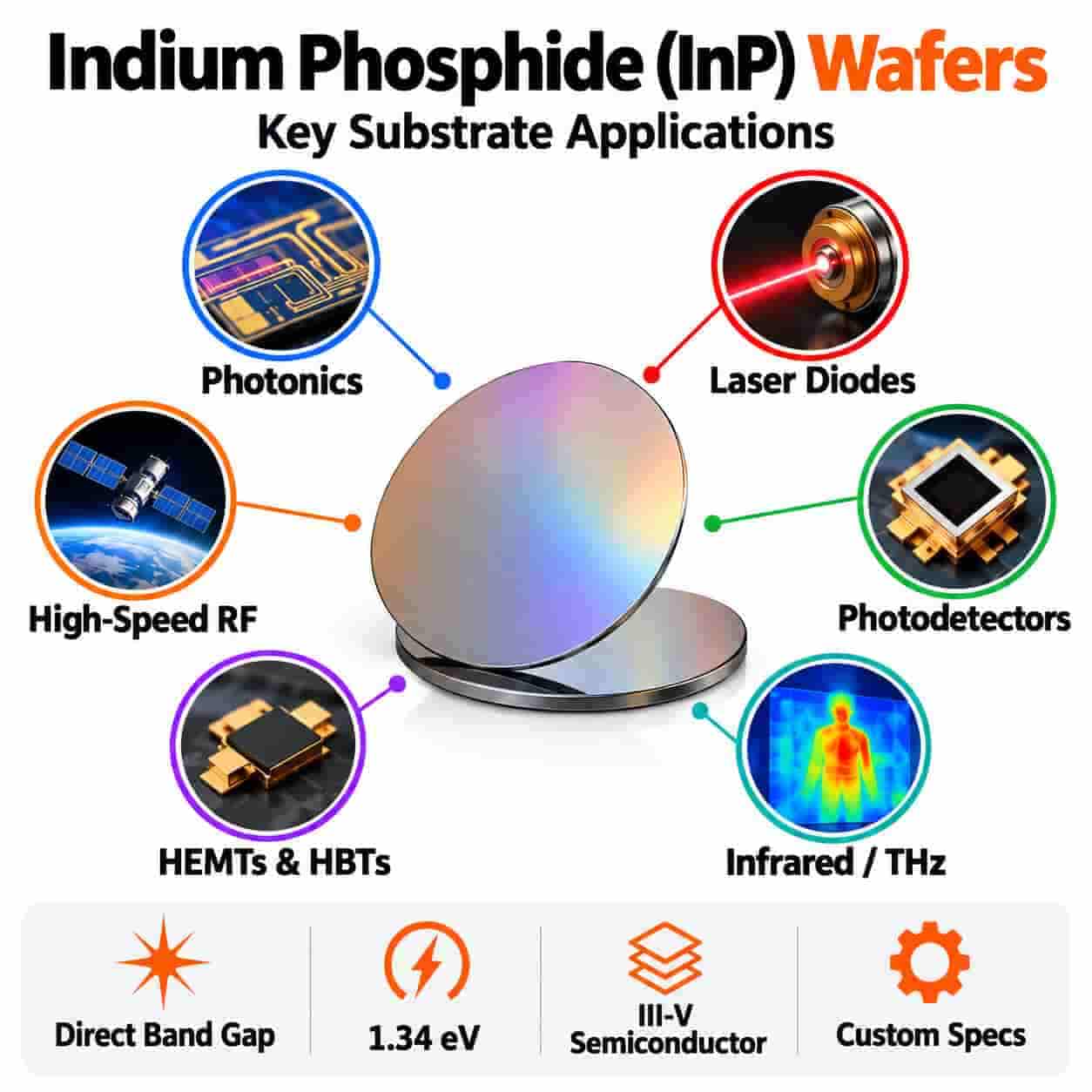
Indium Phosphide Material Properties
| Property | InP |
|---|---|
| Chemical Formula | InP |
| Semiconductor Family | III-V compound semiconductor |
| Crystal Structure | Zinc blende (cubic) |
| Band Gap | Approximately 1.34 eV at room temperature |
| Band-Gap Type | Direct |
| Common Wafer Orientations | (100), (111)A and (111)B, depending on application |
| Conductivity Options | n-type, p-type, nominally undoped and semi-insulating |
| Important Application Areas | Photonics, telecom, lasers, detectors, RF and high-speed electronics |
Material properties vary with temperature, doping, crystal quality, and measurement conditions. Researchers should use the specification for the individual wafer or epitaxial structure when precise values are required.
Why Does the Direct Band Gap of InP Matter?
In a direct-band-gap semiconductor, the conduction-band minimum and valence-band maximum occur at the same crystal momentum. This allows electron-hole transitions involving photons to occur without requiring a phonon to provide the primary momentum change.
This property is one reason III-V semiconductors such as InP and related epitaxial alloys are well suited to light emission, optical gain, and photodetection.
By contrast, silicon has an indirect band gap , which makes efficient light emission from bulk silicon considerably more difficult.
InP as an Epitaxial Substrate
One of the most important roles of an InP wafer is to provide a crystalline substrate for III-V epitaxial heterostructures. Device engineers can grow multiple semiconductor layers with controlled composition, thickness, strain, and doping to produce the electronic and optical properties required for a particular device.
Important InP-compatible material systems include InGaAs , InGaAsP, AlInAs, and related III-V alloys.
These materials can be combined into heterostructures containing quantum wells, barriers, cladding layers, contact layers, absorption regions, and active optical regions. The exact layer design depends on the intended laser, detector, transistor, modulator, or other device.
Indium Phosphide for Photonic Integrated Circuits
Photonic integrated circuits (PICs) combine multiple optical functions on a semiconductor chip. InP-based platforms are particularly valuable because active and passive photonic components can be integrated within related III-V material systems.
Depending on the epitaxial design and fabrication process, an InP-based PIC may incorporate:
- Semiconductor lasers
- Semiconductor optical amplifiers (SOAs)
- Optical modulators
- Photodetectors
- Optical waveguides
- Splitters and couplers
- Wavelength-selective components
- Transmitters and receivers
This capability makes InP especially attractive when a photonic circuit requires an integrated optical source or optical amplification.
Why Is InP Used for Fiber-Optic Communications?
InP is an important substrate platform for optical-communication devices because InP-based heterostructures can be engineered for operation around important telecommunications wavelength bands near 1.3 µm and 1.55 µm.
These wavelengths are important for optical-fiber communication systems. InP-based material systems can support the lasers, modulators, optical amplifiers, and photodetectors needed to generate, transmit, manipulate, and receive optical signals.
In particular, InGaAs and InGaAsP heterostructures grown on or associated with InP are widely used to tailor optical absorption and emission for near-infrared and telecommunications applications.
InP Laser Diodes
InP-based heterostructures are widely used as the foundation for near-infrared semiconductor lasers. Rather than relying only on bulk InP as the light-emitting region, practical devices often use carefully engineered III-V active layers or quantum wells grown on an InP substrate.
Depending on device design, InP-based laser technologies can include:
- Distributed feedback (DFB) lasers
- Fabry-Pérot laser diodes
- Distributed Bragg reflector (DBR) lasers
- Quantum-well lasers
- Photonic integrated laser sources
InP-based material systems are particularly important for laser emission in telecommunications wavelength regions.
InP Photodetectors
InP substrates also support high-performance photodetector structures. In many near-infrared detectors, an InGaAs absorption layer is incorporated into an InP-based heterostructure because its band structure is well suited to detecting important near-infrared wavelengths.
InP-based detector technologies can include PIN photodiodes and avalanche photodiodes (APDs) for applications such as optical receivers, spectroscopy, sensing, and communications.
InP for HEMTs and High-Frequency Electronics
InP substrates are also important for epitaxial structures used to fabricate High Electron Mobility Transistors (HEMTs) .
HEMTs use semiconductor heterojunctions to create a high-mobility electron channel. InP-based heterostructures can provide excellent electron transport characteristics, making them attractive for very-high-frequency, millimeter-wave, and low-noise electronic applications.
Potential research areas include RF electronics, millimeter-wave circuits, high-speed communications, low-noise amplifiers, and terahertz device research.
InP Heterojunction Bipolar Transistors
InP-based material systems are also used for Heterojunction Bipolar Transistors (HBTs) . HBTs use semiconductor materials with different band structures to engineer carrier injection and transport through the transistor.
InP-based HBT technologies are used in research involving high-speed digital electronics, RF and millimeter-wave circuits, optical communication electronics, and other high-frequency systems.
Semi-Insulating InP Substrates
Semi-insulating InP provides high substrate resistivity and can be useful when researchers need electrical isolation between active device regions or want to reduce parasitic conduction through the substrate.
These characteristics can be advantageous for certain RF, microwave, millimeter-wave, and optoelectronic devices. However, the required substrate resistivity and compensation mechanism should be selected according to the specific epitaxial structure and fabrication process.
N-Type and P-Type InP
In addition to semi-insulating material, InP wafers can be supplied with controlled conductivity for device fabrication and epitaxial growth.
| InP Type | Electrical Characteristic | Example Uses |
|---|---|---|
| N-Type InP | Electrons are majority carriers | Conductive substrates, epitaxy and device structures |
| P-Type InP | Holes are majority carriers | Selected optoelectronic and junction structures |
| Semi-Insulating InP | Very high resistivity | Electrical isolation and selected high-frequency devices |
| Nominally Undoped InP | No intentional dopant specified | Research and application-specific epitaxy |
Nominally undoped does not necessarily mean electrically intrinsic. Residual impurities and native defects can still influence carrier concentration and conductivity, so the actual electrical specification of the wafer should always be checked.
InP vs. GaAs vs. Silicon
InP, Gallium Arsenide (GaAs) , and silicon are all important semiconductor materials, but they are optimized for different applications.
| Material | Band-Gap Type | Important Strengths | Example Applications |
|---|---|---|---|
| InP | Direct | Active photonics and high-speed III-V electronics | Telecom lasers, PICs, detectors, HEMTs, HBTs |
| GaAs | Direct | Optoelectronics and high-frequency electronics | RF devices, lasers, LEDs, solar cells |
| Silicon | Indirect | Mature, highly scalable manufacturing ecosystem | CMOS, MEMS, sensors, integrated circuits, silicon photonics |
No single semiconductor is superior for every application. Material selection depends on the required wavelength, carrier transport, device architecture, thermal requirements, fabrication process, integration strategy, and cost.
Integrating InP with Silicon Photonics
InP and silicon can also be used together. Silicon and silicon-on-insulator (SOI) provide mature platforms for passive photonic circuits, while III-V materials can provide efficient active functions such as optical gain and light generation.
Researchers are developing heterogeneous and monolithic integration strategies that combine these strengths. Techniques can include wafer or die bonding, transfer printing, selective epitaxial growth, and other heterogeneous integration processes.
These approaches can enable silicon photonic circuits to incorporate III-V lasers, optical amplifiers, and other active components that are difficult to realize efficiently using silicon alone.
Indium Phosphide Research Applications
InP wafers and InP-based material systems support research across:
- III-V epitaxial growth
- Photonic integrated circuits
- Fiber-optic communications
- Laser diode development
- Photodetectors and optical receivers
- Semiconductor optical amplifiers
- Optical modulators
- RF and microwave electronics
- Millimeter-wave devices
- Terahertz research
- Infrared sensing and spectroscopy
- High-speed transistor research
- III-V/silicon heterogeneous integration
Related Indium Phosphide & III-V Semiconductor Resources
- Indium Gallium Arsenide (InGaAs) – Learn about the III-V alloy widely used with InP for near-infrared photodetectors, high-speed electronics, and epitaxial heterostructures.
- Gallium Arsenide (GaAs) Wafers – Explore another important direct-band-gap III-V semiconductor used for RF electronics, optoelectronics, lasers, and photovoltaic research.
- High Electron Mobility Transistors (HEMTs) – Learn how III-V heterostructures are used to create high-mobility channels for high-frequency transistor applications.
- Heterojunction Bipolar Transistors (HBTs) – Explore heterojunction transistor structures used in high-speed electronic and RF applications.
- Photodetectors – Learn how semiconductor materials and junction structures convert incident optical signals into electrical signals.
- Epitaxial Wafers & Growth – Learn how controlled crystalline layers are grown for advanced semiconductor heterostructures and devices.
- Semiconductor Band Gap – Understand direct and indirect band gaps and their importance to electronic and optoelectronic device behavior.
- Fermi Level – Explore how carrier concentration, doping, and energy bands determine semiconductor electrical behavior.
- Silicon-on-Insulator (SOI) Wafers – Explore the substrate platform widely used for silicon photonics and heterogeneous III-V integration research.
- Silicon Photonics – Learn how silicon-based optical circuits can be combined with III-V active materials for integrated photonic systems.
- High-Performance III-V Devices – Explore III-V materials used for high-speed electronics, optoelectronics, RF devices, and advanced semiconductor research.
- What Is a Semiconductor Wafer? – Learn how crystalline wafers serve as starting substrates for semiconductor epitaxy and device fabrication.