Young's Modulus Substrate Requests
Researchers, engineers, and university laboratories frequently contact UniversityWafer for substrate specifications related to
Young's modulus, elastic modulus, stiffness, crystal orientation, wafer thickness, polish,
surface roughness, and mechanical performance.
Common materials requested for mechanical characterization include
silicon wafers
,
SOI wafers
,
sapphire wafers
,
fused silica wafers
, and
silicon carbide wafers
.
These substrates are used for nanoindentation calibration, finite element analysis, MEMS fabrication, piezoelectric actuators,
deformable mirrors, pressure sensors, resonators, semiconductor packaging, and precision mechanical testing.
Choose Wafers for Mechanical Testing
When requesting a quote, include the substrate material, diameter, thickness, crystal orientation, polish, surface roughness,
quantity, and intended application. These details help determine whether a standard wafer, thick substrate, ultra-thin wafer,
diced piece, optical window, or custom
silicon-on-insulator wafer
is the best option.
-
Select silicon wafers
for MEMS, sensors, deformable structures, semiconductor processing, and orientation-dependent mechanical studies.
-
Select fused silica wafers
for nanoindentation calibration, optical testing, and low-thermal-expansion applications.
-
Select sapphire wafers
for high stiffness, hardness, chemical resistance, and polished mechanical standards.
-
Select SOI wafers
for MEMS actuators, resonators, membranes, sensors, and devices requiring a controlled silicon device layer.
Fused Silica Young's Modulus for Nanoindentation
A materials science engineer requested
fused silica samples
with documented Young's modulus values for nanoindentation calibration.
We previously purchased
fused silica
samples from UniversityWafer and would like additional pieces in different thicknesses.
- Minimum thickness: 5 mm
- Diameter: up to 25 mm
- Square or rectangular pieces: up to 25 mm x 25 mm
- Application: nanoindentation calibration
- Documentation required: elastic modulus or Young's modulus specification sheet
Fused silica is commonly used as a nanoindentation reference material because it provides uniform mechanical properties,
excellent surface quality, low thermal expansion, and a well-characterized elastic modulus of approximately 72 GPa.
Polished fused silica pieces can also be useful for instrument verification, optical testing, and material-property comparisons.
Reference #278853 for specifications and pricing.
Get Your Young's Modulus Substrate Quote FAST!
Or,
Buy Online
and Start Researching Today!
Sapphire Wafer Young's Modulus
A nanomechanical and surface-characterization engineer requested a
single-crystal sapphire wafer
with elastic-modulus information for use as a mechanical testing standard.
We are looking for
single-crystal sapphire
.
Elastic modulus information would be very useful. Small discs with a diameter of 2 cm or larger are preferred.
Purity should be 99% or higher, tilt should be 3° or less, and thickness should be greater than 1 mm.
This material will be used as a mechanical testing standard.
Questions:
- Is the material single-crystal sapphire?
- What does C-A orientation mean?
- Is elastic-modulus information available?
- Is the sapphire wafer polished?
- Is surface-roughness information available?
- What does mechanical grade mean?
- Can a 4 inch sapphire wafer be cut into clean quadrants?
UniversityWafer, Inc. Quoted and Answered:
- The substrate is single-crystal sapphire.
- C-A 2.0° means the C-plane is offcut 2° toward the A-plane.
- Elastic constants were provided as C11 = 496, C12 = 164, C13 = 115, C33 = 498, and C44 = 148.
- Both sides are polished, with a reported surface roughness of less than 0.5 nm.
- Mechanical grade is suitable for mechanical testing, handling, and other non-prime applications.
- The 4 inch wafer can be cut into four clean quadrants for an additional cost.
Sapphire is frequently selected for mechanical testing because it combines high Young's modulus, high hardness,
excellent polish quality, strong chemical stability, and resistance to scratching and wear.
Because sapphire is anisotropic, researchers should specify the required crystal orientation when comparing mechanical-property data.
Reference #277425 for specifications and pricing.
Sapphire Mechanical Property Data Request
An engineering technician requested a complete material specification sheet for a
sapphire wafer
,
including Young's modulus and other physical, thermal, electrical, and mechanical properties.
I would like to know if you can provide a specification sheet for
Sapphire ID 2562
.
- Diameter: 100 mm
- Orientation: C-M plane
- Polish: double-side polished (DSP)
- Thickness: 650 µm
Requested properties included material composition, coefficient of thermal expansion, density, hardness, grain size,
water absorption, gas permeability, flexural strength, elastic modulus, Poisson's ratio, thermal conductivity,
volume resistivity,
dielectric constant
,
and dielectric loss.
A complete sapphire specification is especially useful when the substrate will be used in mechanical simulations,
optical systems, high-temperature applications, RF devices, dielectric testing, or semiconductor fabrication.
Reference #253326 for specifications and pricing.
Young's Modulus of Thick Silicon Wafers
A corporate test and simulation engineer requested
thick silicon wafers
for mechanical modeling, structural testing, and finite element analysis.
We are interested in thick silicon wafers with a thickness of 1.5 mm or greater.
Do you have this type of substrate in stock?
Dopant,
silicon wafer orientation
,
and other specifications are not critical at this stage.
However, documentation explaining how Young's modulus changes with orientation or dopant concentration would be helpful.
For thick silicon wafers used in simulation, crystal orientation generally has a much greater effect on Young's modulus
than moderate changes in dopant concentration. Engineers should select orientation based on the desired stiffness,
bending response, fracture behavior, and mechanical performance of the final structure.
Additional specifications such as thickness tolerance, total thickness variation, bow, warp, edge profile, and surface finish
may also be important when the wafer is used as a mechanical test coupon or structural component.
Reference #263842 for specifications and pricing.
SOI Wafer Young's Modulus for PZT Actuators
A Ph.D. student requested
SOI wafers for PZT actuator fabrication
,
where device-layer stiffness, thickness, crystal orientation, and elastic modulus are important design parameters.
We are studying PZT actuators and would like to know whether
silicon-on-insulator wafers
are available with PZT 5A, 5H, or 5J series materials.
- Device-layer orientation: <100>
- Requested Young's modulus: 135 GPa
- Device-layer thickness: 20 µm
- Buried oxide thickness: 2 µm thermal oxide
- Handle-layer thickness: greater than 500 µm
-
Polish:
single-side polished (SSP)
- Device-layer resistivity: 0.001–0.005 Ohm-cm
- Handle layer: undoped
- PZT coating thickness: 0.5–1 µm
- Wafer diameter: 4 inch
- Device-layer conductivity type: n-type
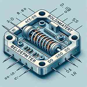
SOI wafers are widely used in piezoelectric actuators,
MEMS devices,
resonators, pressure sensors, accelerometers, and microelectromechanical structures.
The buried oxide electrically isolates the silicon device layer while also acting as an etch-stop layer during fabrication.
Young's modulus is used in finite element analysis to predict actuator displacement, structural stiffness,
resonant frequency, membrane deflection, and the mechanical response of the silicon device layer.
For accurate modeling, researchers should also account for the PZT film, electrodes, residual stress, and multilayer geometry.
Reference #259871 for specifications and pricing.
Young's Modulus of <100> and <111> Silicon Wafers
A doctoral student requested
ultra-thin silicon wafers
for deformable-mirror research and asked whether Young's modulus is the same for Si <100> and Si <111> orientations.
We need the following thin silicon wafers:
- 100 µm ±1 µm, 6 inch silicon wafer, DSP
- 25 µm ±1 µm, 6 inch silicon wafer, DSP
The wafers will be used for deformable mirrors. Flat and smooth substrates are preferred, and doping is not required.
For reporting purposes, we would also like to know the crystal structure.
We initially assumed that Young's modulus was nearly the same for Si <111> and Si <100>.
UniversityWafer, Inc. Replied:
Single-crystal
silicon wafers
are mechanically anisotropic. This means their Young's modulus changes with crystal orientation and the direction of loading.
The difference is important for deformable mirrors, MEMS devices, pressure sensors, resonators, wafer thinning,
diaphragms, cantilevers, and other precision mechanical structures.
- <100> silicon: approximately 130 GPa
- <110> silicon: approximately 169 GPa
- <111> silicon: approximately 187.5–188 GPa
The
<111> silicon orientation
is significantly stiffer than <100> silicon.
This difference should be included in mechanical simulations because orientation can influence bending stiffness,
mirror deformation, resonant frequency, fracture behavior, and device sensitivity.
Engineers selecting wafers for
MEMS fabrication
,
deformable mirrors, thin diaphragms, membranes, resonators, and precision structures should specify the required
silicon crystal orientation rather than relying on a single generic modulus value.
Silicon Young's Modulus and Wafer Stiffness
The Young's modulus of silicon, also called its elastic modulus, typically ranges from approximately
130 GPa to 188 GPa, depending on the crystal orientation and the direction of the applied force.
This property describes how strongly a material resists elastic deformation and is an important consideration when selecting
silicon wafers
for semiconductor fabrication, mechanical testing, MEMS devices, sensors, resonators, and structural simulation.
Researchers selecting silicon substrates for mechanical applications should consider
silicon wafer orientation,
thickness, diameter, polish, surface roughness, total thickness variation, bow, warp, and whether the material will be used as a
bulk wafer, an ultra-thin membrane, or the device layer of an
SOI wafer.
Stress, Strain, and Young's Modulus
Stress and strain describe different parts of a material's response to an applied force.
Stress is the applied force divided by the cross-sectional area and is generally measured in Pascals.
Strain is the resulting change in length divided by the original length and is dimensionless.
Within the elastic region, Young's modulus is calculated from the ratio of stress to strain.
A material with a high Young's modulus is relatively stiff and undergoes less elastic deformation under the same load,
while a material with a lower modulus bends or stretches more easily.
This relationship is especially important when modeling wafer bending, thin membranes, cantilevers, pressure-sensor diaphragms,
microbridges, resonators, optical mirrors, and other semiconductor structures that must maintain precise dimensions.
Elastic Deformation vs. Permanent Damage
During elastic deformation, a substrate returns to its original dimensions after the applied force is removed.
Young's modulus describes material behavior within this reversible range.
When the stress exceeds the material's allowable limit, permanent deformation, cracking, chipping, or fracture may occur.
Semiconductor and optical substrates such as silicon,
sapphire wafers,
fused silica wafers,
and silicon carbide are brittle materials and generally fracture before undergoing substantial plastic deformation.
Understanding elastic behavior and fracture risk helps engineers choose suitable wafer materials for MEMS fabrication,
semiconductor packaging, optical windows, microfluidic devices, high-temperature electronics, and precision sensors.
Young's Modulus of Common Wafer Materials
Wafer materials offer different combinations of stiffness, thermal stability, optical transmission, electrical behavior,
chemical resistance, and fabrication compatibility. The values below are approximate and may vary with orientation,
composition, temperature, and measurement method.
Young's Modulus of Silicon by Crystal Orientation
Single-crystal silicon is mechanically anisotropic, meaning its apparent stiffness depends on the crystal direction
and loading direction. Engineers should not assume that every silicon wafer has the same Young's modulus.
The difference between <100>, <110>, and <111> silicon can affect wafer bending, resonant frequency,
actuator displacement, membrane deflection, fracture behavior, and finite element analysis results.
The greater stiffness of <111> silicon can be beneficial when minimizing elastic deflection is important.
In comparison, <100> silicon is widely selected because of its compatibility with conventional integrated-circuit processing,
oxidation, etching, and MEMS fabrication.
Factors That Affect Measured or Effective Modulus
Young's modulus is an intrinsic material property, but the measured value or the effective stiffness of a fabricated structure
can be influenced by several material, process, and device-design factors.
- Crystal orientation, particularly for silicon, sapphire, quartz, and other single-crystal substrates
- Direction of the applied force relative to the crystal axes
- Operating and testing temperature
- Crystal defects, inclusions, and material purity
- Residual stress from oxide, nitride, metal, or piezoelectric thin films
- Porosity and microstructure
- Layer thicknesses in SOI wafers and other multilayer substrates
- Wafer thickness, bow, warp, and total thickness variation
- Measurement method, including nanoindentation, bending, tensile testing, and acoustic methods
Moderate changes in dopant concentration generally have less influence on the Young's modulus of crystalline silicon than
crystal orientation, temperature, or device geometry. However, highly processed, porous, damaged, or multilayer structures
may exhibit an effective stiffness that differs from bulk silicon.
Choosing Wafers Based on Young's Modulus
The best wafer material depends on the stiffness, optical, electrical, thermal, and fabrication requirements of the application.
UniversityWafer supplies substrates for mechanical characterization, device fabrication, university laboratories, and industrial research.
-
Choose
silicon wafers
for CMOS-compatible processing, MEMS, sensors, photonics, and general semiconductor research.
-
Choose
SOI wafers
when a precisely controlled silicon device layer and buried oxide are required for MEMS, resonators, actuators, or microfluidic devices.
-
Choose
sapphire wafers
for high stiffness, hardness, optical transparency, thermal stability, or chemically resistant substrate applications.
-
Choose
silicon carbide wafers
for very high stiffness, high-temperature operation, power electronics, and harsh-environment devices.
-
Choose
fused silica wafers
for nanoindentation calibration, low thermal expansion, photonics, optical windows, and transparent microfluidic devices.
-
Choose
ultra-thin silicon wafers
for deformable mirrors, membranes, flexible structures, lightweight devices, and bending studies.
Applications of Young's Modulus in Semiconductor Research
Mechanical characterization supports material selection, process development, and device-reliability modeling throughout
semiconductor manufacturing. Researchers use elastic-modulus data to predict wafer stress, bending, vibration, displacement,
fracture risk, and structural stability.
-
MEMS fabrication
- Nanoindentation calibration and hardness testing
- Finite element analysis (FEA)
- Wafer thinning and back-grinding studies
- Semiconductor packaging and die-attach analysis
- Optical windows and precision mirror structures
- Piezoelectric actuators and PZT devices
- Power semiconductor devices
- Pressure sensors and thin diaphragms
- Microfluidic and lab-on-chip devices
- Silicon photonics and optical MEMS
- Resonators, cantilevers, and accelerometers
- Wafer bow, warp, and residual-stress analysis
Accurate modulus values allow engineers to improve simulation results, compare candidate wafer materials, optimize device dimensions,
and reduce the risk of cracking, excessive deformation, or mechanical failure before fabrication begins.
Frequently Asked Questions About Young's Modulus
Is Young's modulus the same as stiffness?
Not exactly. Young's modulus describes the stiffness of the material itself. The stiffness of a finished component also depends on
its dimensions, thickness, shape, support conditions, and loading direction.
Does every silicon wafer have the same Young's modulus?
No. Single-crystal silicon is anisotropic, so its elastic modulus changes with crystal orientation and loading direction.
Wafer orientation should therefore be included in mechanical simulations and device-design calculations.
Does wafer thickness change Young's modulus?
Wafer thickness does not normally change the intrinsic Young's modulus of bulk crystalline silicon.
However, thickness strongly affects the bending stiffness and deflection of the wafer or finished structure.
Why is fused silica used for nanoindentation calibration?
Fused silica has uniform mechanical properties, excellent surface quality, low thermal expansion, and a well-characterized
elastic modulus. These qualities make it a common reference material for nanoindentation instruments.
Which common wafer material has the highest Young's modulus?
Among the common materials listed on this page,
silicon carbide wafers
have one of the highest Young's modulus ranges. This high stiffness supports power electronics, harsh-environment sensors,
high-temperature devices, and mechanically demanding MEMS applications.
What wafer specifications should be provided when requesting a quote?
Useful specifications include material, wafer diameter, thickness, crystal orientation, dopant type, resistivity, polish,
surface roughness, total thickness variation, bow, warp, quantity, and the intended mechanical or semiconductor application.
Buy Wafers for Mechanical Testing and Device Fabrication
UniversityWafer supplies
silicon wafers,
SOI wafers,
sapphire wafers,
silicon carbide wafers,
fused silica wafers,
and optical glass substrates for mechanical testing, MEMS, photonics, semiconductor fabrication, nanoindentation,
high-temperature electronics, and university research.
Substrates are available in research and production quantities with custom options for diameter, thickness, orientation,
polishing, surface finish, dicing, and other specifications.
Contact UniversityWafer for pricing and availability
or
buy wafers online
.
Related Wafer and Semiconductor Resources
